
LED (light-emitting diode ) lamp bar and backlight module

A technology of LED light strips and LED modules, applied in optics, nonlinear optics, instruments, etc., can solve problems such as evaluation errors, waste of resource costs, development cycle, and failure to share light strips, so as to avoid waste of resources and shorten development cycle effect

Inactive Publication Date: 2016-11-09
KUSN INFOVISION OPTOELECTRONICS
View PDF8 Cites 6 Cited by
  • Summary
  • Abstract
  • Description
  • Claims
  • Application Information

AI Technical Summary

Problems solved by technology

[0004] The LED light strips used in the current LCD backlight modules are all of fixed length, and the distance between each LED is fixed. The light strips of different models cannot be shared. Therefore, when a new model is opened for evaluation, only Approximate evaluation based on similar models, so there is a relatively large evaluation error, and the quality status (hotspot, vignetting, etc.) cannot be predicted in advance, so when the actual production needs to adjust the number of LEDs or the spacing between LEDs, The light bar needs to be redesigned and made, which has the problem of wasting resources, cost and development cycle

Method used


Image

  • LED (light-emitting diode ) lamp bar and backlight module
  • LED (light-emitting diode ) lamp bar and backlight module
  • LED (light-emitting diode ) lamp bar and backlight module

Examples


Embodiment Construction

[0025] Various embodiments of the invention will be described in more detail below with reference to the accompanying drawings. In the various drawings, the same elements are denoted by the same or similar reference numerals. For the sake of clarity, various parts in the drawings have not been drawn to scale.

[0026] figure 1 A schematic structural diagram of the first embodiment of the LED light bar provided by the present invention.

[0027] Such as figure 1 As shown, the LED light bar provided by the present invention includes a substrate 100 , an LED module 200 and a fixing block 300 . There are multiple LED modules 200 . The fixing block 300 is arranged between two adjacent LED modules 200 and fixed on the substrate 100 for controlling the distance between two adjacent LED modules 200 .

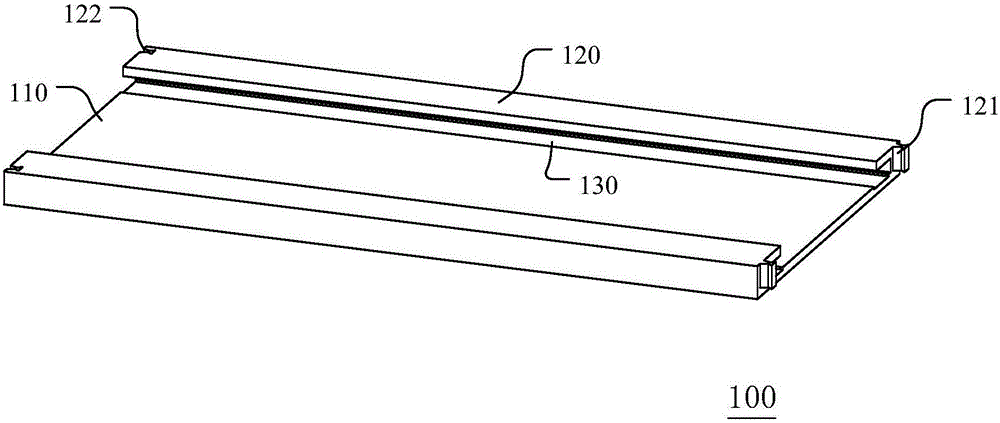
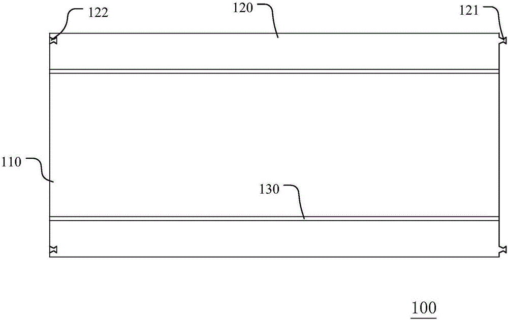
[0028] figure 2 It is a schematic diagram of the substrate structure of the first embodiment of the LED light bar provided by the present invention, image 3 A schematic top view...


PUM


Abstract

The invention relates to an LED (light-emitting diode ) lamp bar. The LED lamp bar comprises a substrate, a plurality of LED modules and a plurality of fixed blocks, wherein the LED modules are arranged on the substrate and are electrically connected to the substrate; each fixed block is arranged between two adjacent LED modules and is fixed on the substrate. Through a modular design of parts of the LED lamp bar, parameter such as interval and the number of LEDs and length of the lamp bar can be conveniently adjusted. The LED lamp bar is applicable to a variety of machine types; meanwhile, batch production of the LED lamp bars can be achieved; the production period of the lamp bars is shortened, and the production cost of the lamp bars is reduced.

Description

technical field [0001] The invention relates to the technical field of liquid crystal display, in particular to an LED light bar and a backlight module. Background technique [0002] In recent years, with the rapid development of flat-panel display technology, liquid crystal displays (LCDs) have been widely used in various information and communication consumer products due to their advantages of small size, high image quality, no radiation, and low driving voltage. Since the liquid crystal display panel in the LCD itself does not emit light, a backlight module needs to be installed on the back of the liquid crystal display panel as a backlight source to display images normally. [0003] With the rapid development of light source technology in backlight modules, light-emitting diodes (LEDs) have gradually replaced cold cathode fluorescent lamps (CCFLs) due to their low energy consumption, small size, long life, and low temperature rise. Form as a backlight for liquid crysta...

Claims


Application Information

Patent Timeline
Patent Type & Authority Applications(China)
IPC IPC(8): G02F1/13357
CPCG02F1/133603G02F1/133615
Inventor 陆敏白晓鸽王小荣
Owner KUSN INFOVISION OPTOELECTRONICS
Learn More