
Device for jointly removing SO3 and dust in inlet smoke of SCR denitration device

A combined removal and flue gas technology, applied in gas treatment, membrane technology, dispersed particle separation, etc., can solve problems such as easy blockage of absorption liquid supply pipe, exit of SCR denitrification device, reduction of catalyst chemical activity, etc., to achieve equipment and operation Low maintenance cost, small equipment changes, rich mineral resources

Inactive Publication Date: 2016-11-16
HUADIAN ELECTRIC POWER SCI INST CO LTD
View PDF4 Cites 5 Cited by
  • Summary
  • Abstract
  • Description
  • Claims
  • Application Information

AI Technical Summary

Problems solved by technology

[0007] (1) Do not use SO before the SCR denitrification device 3 Control technology, leading to the shutdown of the SCR denitrification device in the medium and low load conditions of the unit
[0008] (2) Spraying alkaline absorbent before the SCR denitrification device may reduce the chemical activity of the catalyst or even deactivate the catalyst
[0009] (3) The flue gas with high dust content will wear the catalyst in the process of flowing through the catalyst, which will affect the normal operation of the equipment and increase the operating cost
[0010] (4) The method of using trona solution as the absorbent is limited by conditions such as the site and the concentration of the absorption solution, the supply pipe of the absorption solution is easily blocked, and the system is complicated

Method used


Image

  • Device for jointly removing SO3 and dust in inlet smoke of SCR denitration device

Examples


Embodiment Construction

[0021] The present invention will be further described in detail below in conjunction with the examples, the following examples are explanations of the present invention and the present invention is not limited to the following examples.

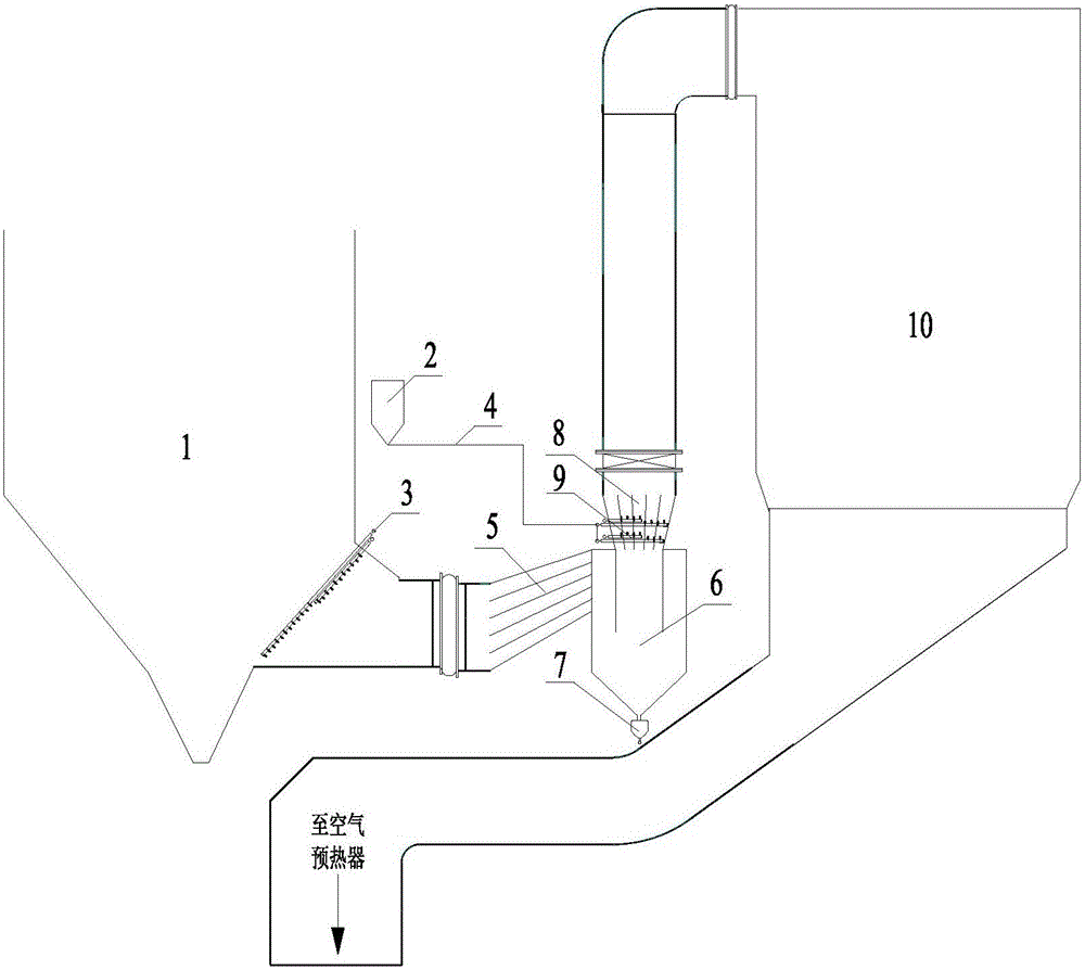
[0022] Such as figure 1 As shown, in this embodiment, the joint removal of SO in the flue gas at the inlet of the SCR denitrification device 3 The device for removing dust and dust includes economizer and its ash hopper 1, absorbent storage device 2, absorbent injection system 3, absorbent delivery system 4, cyclone dust collector inlet flue 5, cyclone dust collector 6, warehouse pump and pneumatic conveying system Ash pipeline 7, cyclone outlet flue 8, ammonia injection grid 9, denitrification reactor 10.

[0023] Arrange absorbent injection system 3 at the outlet of flue gas 1 in the ash hopper of the economizer to inject SO 3 The absorbent trona, the anti-wear plate on the windward side of the absorbent injection system also has the fun...


PUM


Abstract

The invention relates to a device for jointly removing SO3 and dust in inlet smoke of a SCR (Selective Catalytic Reduction) denitration device. The device comprises a coal economizer, an ash bucket, an absorbent storage, an absorbent spraying system, an absorbent conveying system, a cyclone dust collector inlet flue, a plurality of cyclone dust collectors, a cyclone dust collector outlet flue and an SCR denitration reactor, wherein the coal economizer, the ash bucket, the absorbent spraying system, the cyclone dust collectors and the SCR denitration reactor are successively connected with each other through a flue; natural alkali serving as an absorbent fills the absorbent storage; the absorbent spraying system is arranged at a smoke outlet of the ash bucket of the coal economizer; the cyclone dust collectors are arranged on the flue of the absorbent spraying system close to the inlet of the SCR denitration reactor. The device further comprises an ammonia spraying grid arranged on the cyclone dust collector outlet flue. The daily consumed raw materials of the device provided by the invention are rich in mineral resources and low in cost; the cyclone dust collector technique is mature and the device is reliable; the change in the current device and unit is small; the specially-assigned person for operation is not required; the running cost and maintenance cost of the device are low.

Description

technical field [0001] The invention relates to a combined removal of SO in flue gas at the inlet of an SCR denitrification device 3 And smoke and dust devices, which belong to the field of environmental protection equipment. Background technique [0002] On February 29, 2016, the National Bureau of Statistics issued the 2015 Statistical Bulletin on National Economic and Social Development. According to the bulletin data, in 2015, the national raw coal output was 3.75 billion tons, the coal export volume was 5.33 million tons, and the export value was 3.1 billion yuan; the coal import volume was 204.06 million tons. In the past 6 years, coal production has remained at more than 3.4 billion tons, and the supply pattern of coal as the main energy source in my country will not change for a long time in the future. However, a large amount of harmful substances are produced in the process of coal combustion, especially in the thermal power industry, the flue gas after coal comb...

Claims


Application Information

Patent Timeline
Patent Type & Authority Applications(China)
IPC IPC(8): B01D53/83B01D53/50B01D45/12B01D53/90B01D53/86B01D53/56
CPCB01D53/83B01D45/12B01D53/50B01D53/8631B01D53/90B01D2258/0283
Inventor 刘沛奇何胜郑文广李乾坤
Owner HUADIAN ELECTRIC POWER SCI INST CO LTD
Learn More