Check patentability & draft patents in minutes with Patsnap Eureka AI!

Transverse constant current device with self-protection function at three terminals and manufacturing method thereof

A protection function, constant current device technology, applied in semiconductor/solid state device manufacturing, semiconductor devices, electric solid state devices, etc., can solve the problems of low constant current, low breakdown voltage, easy to burn, etc., to reduce area and improve reliability the effect of reducing R&D costs

Active Publication Date: 2019-04-12
UNIV OF ELECTRONICS SCI & TECH OF CHINA
View PDF4 Cites 0 Cited by
  • Summary
  • Abstract
  • Description
  • Claims
  • Application Information

AI Technical Summary

Problems solved by technology

However, the current high breakdown voltage of constant current diodes is generally 30-100V, so there is a problem of low breakdown voltage, and the constant current that can be provided is also low, and most constant current diodes cannot cope with the harsh external environment. , it is easy to burn out when it is struck by lightning or the large voltage and high current generated by the fluctuation of the power grid, which makes it difficult to guarantee the safety of the subsequent drive circuit. A transient voltage suppressor (TVS, Transient Voltage Suppressor) is integrated outside the constant current diode Finally, the anti-surge capability of the constant current diode and the entire drive system can be enhanced, and the reliability is greatly improved

Method used


Image

  • Transverse constant current device with self-protection function at three terminals and manufacturing method thereof
  • Transverse constant current device with self-protection function at three terminals and manufacturing method thereof
  • Transverse constant current device with self-protection function at three terminals and manufacturing method thereof

Examples


Embodiment Construction

[0036] Embodiments of the present invention are described below through specific examples, and those skilled in the art can easily understand other advantages and effects of the present invention from the content disclosed in this specification. The present invention can also be implemented or applied through other different specific implementation modes, and various modifications or changes can be made to the details in this specification based on different viewpoints and applications without departing from the spirit of the present invention.

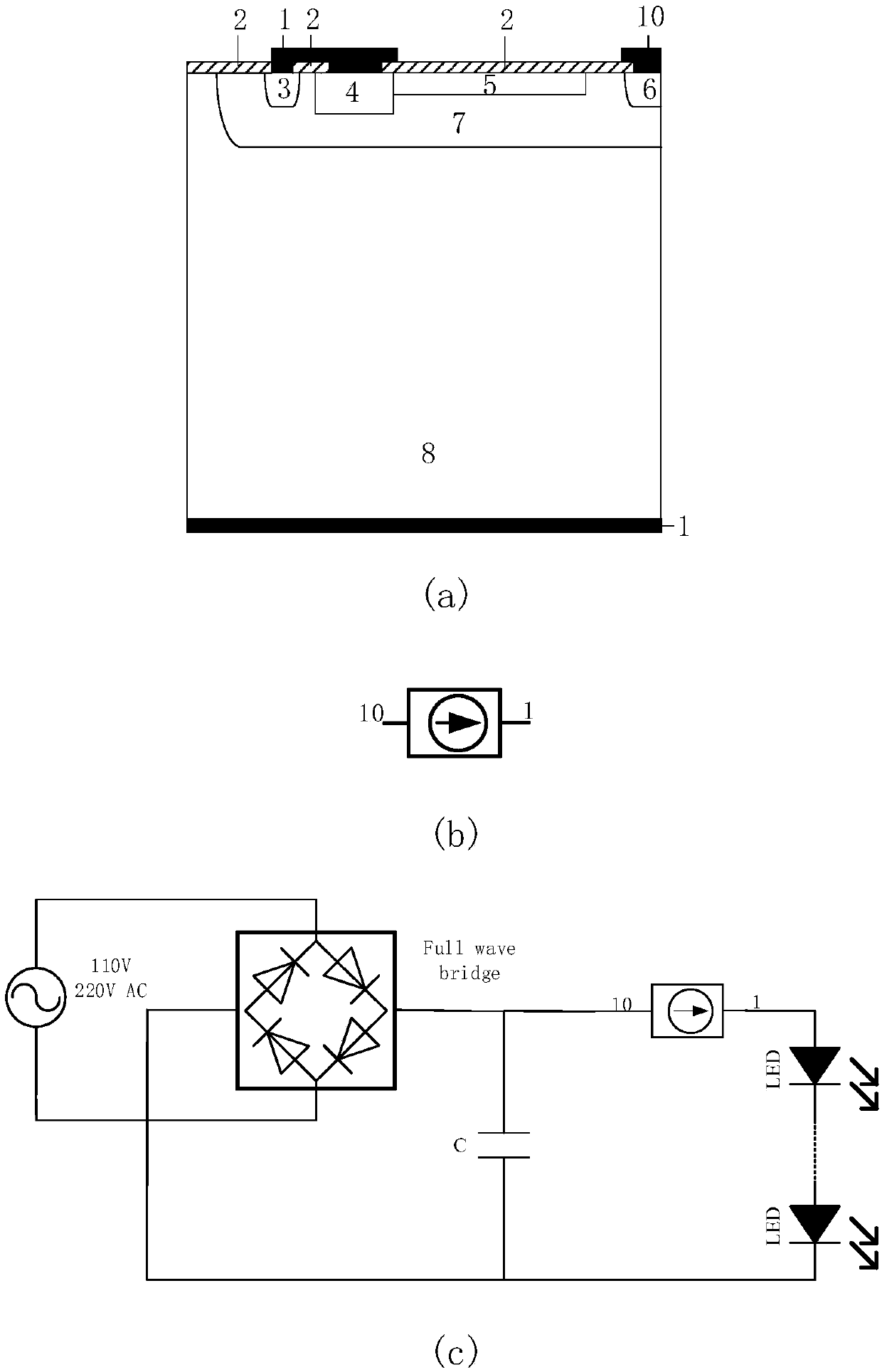
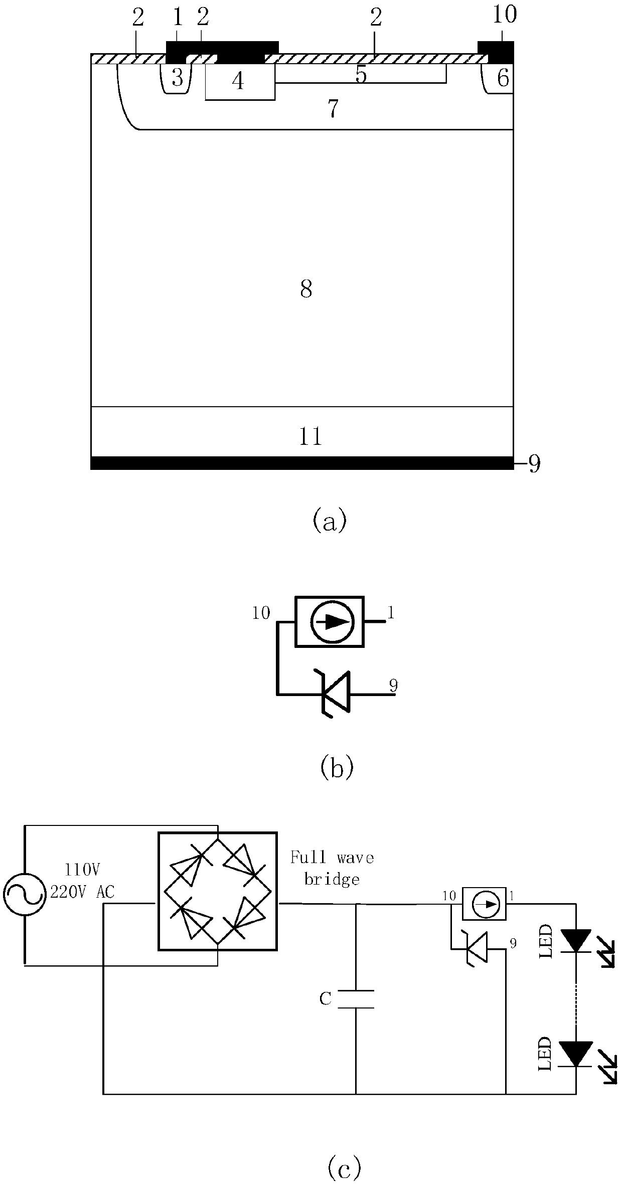
[0037] figure 1 For the traditional vertical constant current diode, figure 1 There are 3 sub-figures (a), (b) and (c) respectively, which are the traditional device structure diagram at both ends horizontally, the symbol diagram of the constant current diode, and the applied LED drive circuit; figure 2 It is a lateral constant current device with a protective function at three terminals of the present invention, figure 2 There ar...


PUM


Abstract

The invention provides a lateral constant current device with three terminals with self-protection function and its manufacturing method. The device includes a lateral constant current diode structure and a transient voltage suppression diode structure. The lateral constant current diode includes a P-type lightly doped substrate, a second A P-type heavily doped region, a second metal cathode, a diffused N-type well region, a second P-type heavily doped region, a third P-type lightly doped region, a first N-type heavily doped region, a second N-type The heavily doped region, the oxide dielectric layer, and the first metal cathode; the transient voltage suppression diode structure includes a P-type lightly doped substrate, a first P-type heavily doped region, a second metal cathode, a diffused N-type well region, and a second Two N-type heavily doped regions, oxidized dielectric layers, and metal anodes; the present invention breaks down first when surge fluctuations attack the constant current device, and discharges the amplified current to protect the constant current diode and the LED light string driven thereafter, improving the The reliability of the constant current device and the whole system greatly reduces the area and reduces the cost of research and development.

Description

technical field [0001] The invention belongs to the technical field of semiconductor power devices, and in particular relates to a lateral constant current device with protective functions at three terminals and a manufacturing method thereof. Background technique [0002] The constant current source is a commonly used electronic equipment and device, and it is widely used in electronic circuits. The constant current source is used to protect the entire circuit, even if the voltage is unstable or the load resistance changes greatly, it can ensure the stability of the supply current. However, the current high breakdown voltage of constant current diodes is generally 30-100V, so there is a problem of low breakdown voltage, and the constant current that can be provided is also low, and most constant current diodes cannot cope with the harsh external environment. , it is easy to burn out when it is struck by lightning or the large voltage and high current generated by the fluct...

Claims


Application Information

Patent Timeline
Patent Type & Authority Patents(China)
IPC IPC(8): H01L29/861H01L21/329H01L21/77H01L27/06
CPCH01L21/77H01L27/06H01L29/6609H01L29/861
Inventor 乔明李成州卢璐于亮亮张波
Owner UNIV OF ELECTRONICS SCI & TECH OF CHINA
Features
  • R&D
  • Intellectual Property
  • Life Sciences
  • Materials
  • Tech Scout
  • Unparalleled Data Quality
  • Higher Quality Content
  • 60% Fewer Hallucinations
Learn More