

Adaptive hysteresis sliding-mode control method for double-tube Buck-Boost converter
A control method and converter technology, applied in control/regulation systems, DC power input conversion to DC power output, instruments, etc., can solve problems such as excessive power loss, electromagnetic interference, and switching frequency instability, and avoid design Sophisticated, well tuned and dynamic performance, enhanced stability and robustness effects
- Summary
- Abstract
- Description
- Claims
- Application Information
AI Technical Summary
Problems solved by technology
Method used
Image

Examples
specific Embodiment approach 1
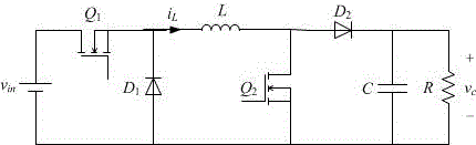
[0017] Specific implementation mode one: the following combination figure 1 Explain the establishment process of the mathematical model of the dual-tube Buck-Boost converter. The dual-tube Buck-Boost converter is obtained by cascading and simplifying the Buck converter and the Boost converter. According to the comparison between the input voltage and the ideal output voltage, the converters can work separately in Buck mode and Boost mode.
[0018] (1) When the input voltage is higher than the output voltage, the controllable switch Q 2 kept open, the diode D 2 conduction, control the controllable switch Q 1 To adjust the output voltage, the converter is equivalent to a Buck converter, and the mathematical model of the converter in Buck mode satisfies:
[0019] (1)
[0020] Wherein, the L is the filter inductance, C is the filter capacitor, R is the load resistance, v in is the instantaneous value of the input voltage, v c is the instantaneous value of the output volta...
specific Embodiment approach 2
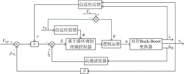
[0026] Specific implementation mode two: according to the i in the mathematical model L and v c , construct the control trajectory function S, so that S satisfies:
[0027] (4)
[0028] Among them, the I L is the DC component of the inductor current, α is the positive control coefficient, called the sliding coefficient, V ref is the reference output voltage, β is the proportional coefficient of the output voltage sampling circuit, and satisfies V ref =β×V o , V o is the ideal output voltage value.
[0029] In the actual circuit, let the sampled inductor current i L After a high-pass filter, to equivalently obtain i L −I L .
specific Embodiment approach 3
[0030] Embodiment 3: The entire sliding mode movement can be divided into two stages. In the first stage (called the arrival stage), regardless of the initial position of the control trajectory S, the sliding mode control will force the trajectory to move to the sliding manifold. This process can only be realized if the arrival condition is met.
[0031] The arrival condition requires that the selected control decision guides the trajectory of the system to approach and eventually reach the sliding manifold, that is, to satisfy:
[0032] (5)
[0033] (1) When S>0, from formula (5), it needs to satisfy , from formula (4), it needs to satisfy:
[0034] (6)
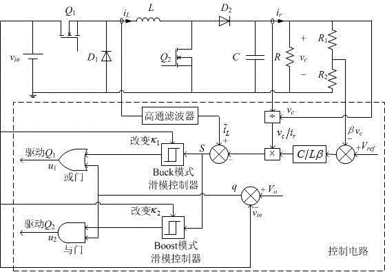
[0035] When the converter is in Buck mode, it needs to satisfy , the controllable switch Q 1 The control signal u 1 =0; when the converter is in Boost mode, it needs to satisfy , the controllable switch Q 2 The control signal u 2 =1.
[0036] (2) When S , from formula (4), it needs to satisfy:
[0037] ...
PUM
 Abstract
Description
Claims
Application Information