Fan assembling machine

A technology for fan groups and components, applied in assembly machines, metal processing equipment, manufacturing tools, etc., can solve the problems of reducing work efficiency, a lot of manpower, and increasing costs, and achieve the effects of convenient operation, stable work performance, and high work efficiency.

Active Publication Date: 2016-11-23
SHANGHAI ZHAOCHENG COMMUTATOR TECH
View PDF5 Cites 11 Cited by
  • Summary
  • Abstract
  • Description
  • Claims
  • Application Information

AI Technical Summary

Problems solved by technology

[0003] At present, cooling fans need to be assembled during the production process. Generally, cooling fans are composed of shells, upper bearings, fan blade rotors, lower bearings, backing rings and retaining springs. Due to the small parts in the fan asse...

Method used


Image

  • Fan assembling machine
  • Fan assembling machine
  • Fan assembling machine

Examples


Embodiment Construction

[0018] Below in conjunction with accompanying drawing, the present invention is further described:

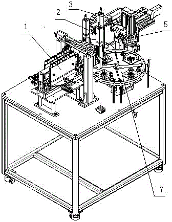
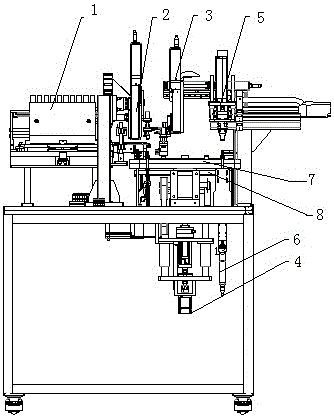
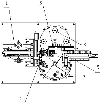
[0019]As shown in the drawings, a fan assembly machine is equipped with a frame, which is characterized in that the frame is equipped with a bearing feeding mechanism 1, a bearing transport mechanism 2, a blade rotor pressing mechanism 3, a lower bearing and a clamping mechanism. The three-piece pressing mechanism 4 of the spring and the backing ring, the finished product unloading mechanism 5, the image detection mechanism 6 and two rotary disks are composed. The sensor 11 and the material cutting cylinder 12 are composed, and the bearing pushing assembly 10 is composed of a linear sliding assembly 13, a material cutting jig 14, a rodless cylinder 15 and a guide rod 16, and the rodless cylinder 15 is controlled by a three-position mid-release solenoid valve to drive the cutting machine. The material fixture 14 pushes the bearing to move forward, and the bearing moves forward b...


PUM


Abstract

The invention relates to the technical field of semi-automatic assembly of cooling fans, in particular to a fan assembling machine. The fan assembling machine comprises a rack and is characterized in that a bearing loading mechanism, a bearing carrying mechanism, a blade rotor pressing-in mechanism, a lower bearing, snap spring and backing ring pressing-in mechanism, a finished product unloading mechanism, an image detecting mechanism and two rotating disks are arranged on the rack; the bearing loading mechanism comprises a bearing casing pipe group, a bearing pushing assembly, a laser sensor, a front cutting air cylinder and a back cutting air cylinder; and all the mechanisms share the work and cooperate with one another, casings and fan blade rotors are manually placed on the discharging station of the upper rotating disk, snap springs, backing rings and lower bearings are manually placed on the discharging station of the lower rotating disk, and other assembling actions are completed automatically. The machine has the advantages of being convenient to operate, high in working efficiency, stable in working performance, capable of realizing semi-automatic assembly and the like.

Description

technical field [0001] The invention relates to the technical field of semi-automatic assembly of cooling fans, in particular to a fan assembly machine with convenient operation, high work efficiency, stable work performance and semi-automatic assembly. Background technique [0002] As we all know, with the development of modernization, computers, communication products, optoelectronic products, consumer electronics, automotive electronic equipment, switches, medical equipment, heaters, air conditioners, frequency converters, teller machines, car freezers, welding machines, induction cookers, audio equipment Traditional or modern instruments and equipment such as environmental protection equipment and refrigeration equipment have undergone tremendous development, especially these traditional or modern instruments and equipment are equipped with cooling fans. Therefore, the demand for cooling fans is getting higher and higher with the development of modernization. [0003] At...

Claims


Application Information

Patent Timeline
IPC IPC(8): B23P21/00
CPCB23P21/006
Inventor 徐朝明李胜勇
Owner SHANGHAI ZHAOCHENG COMMUTATOR TECH
Why Eureka
Try Eureka