Defrosting method of air source heat pump water heater
An air source heat pump and water heater technology, applied in fluid heaters, lighting and heating equipment, damage protection, etc., can solve the problems of heat pump working fluid evaporation temperature drop, large errors, and different effects.
- Summary
- Abstract
- Description
- Claims
- Application Information
AI Technical Summary
Problems solved by technology
Method used
Image
Examples
Embodiment 1
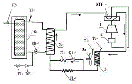
[0043] The air source heat pump water heater system of Embodiment 1 includes compressor 1, four-way valve STF, hot water condensation heat exchanger 2, throttle J1, air source fin heat exchanger 3, and air source fin heat exchanger Fan 3a, gas-liquid separator 4, mild throttle J2, one-way valve D1, hot water storage tank 6, circulating water pump SB, characterized in that it is arranged with a mild throttle reverse flow bypass and throttle J1 is connected in parallel, and a mild restrictor J2 and a one-way valve are installed on the bypass, and the flow direction of the one-way valve D1 points to the hot water condensation heat exchanger; the refrigerant process of the anti-heat pump cycle defrosting is: compressor 1 → Four-way valve STF → Air source fin heat exchanger 3 → One-way valve D1 → Mild restrictor J2 → Hot water condensation heat exchanger 2 → Four-way valve → Gas-liquid separator 4 → Compressor; An ambient air temperature probe T1 is arranged on the casing of the so...
Embodiment 2
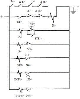
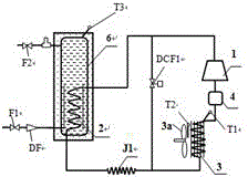
[0045] The air source heat pump water heater system of Embodiment 2 includes a compressor 1, a hot water condensation heat exchanger 2, a throttle J1, an air source fin heat exchanger 3, a fan 3a of the air source fin heat exchanger, an air-liquid Separator 4, hot water storage tank 6, hot water condensation heat exchanger 2 placed in hot water storage tank 6, defrosting bypass valve DCF1; the lower end interface between the compressor exhaust port and the air source fin heat exchanger Between, add a defrost bypass with a defrost bypass valve installed in parallel with the throttle; figure 1 The control circuits shown in lines 1, 2, 4, and 6; when the four defrosting conditions are all met, that is, the four normally open signal contacts T a ,Δ T , τ and Δ t 1 When both are closed, after the system sends a defrosting signal command, the defrosting starts, the coil N of the defrosting relay is energized, the third contact N3 of the defrosting relay is opened, and the fan...
Embodiment 3
[0047] The refrigerant circulation system of the air source heat pump water heater in embodiment 3 is the same as that in embodiment 2, the difference is that hot water spray is used for defrosting; The road is a separate hot water pipeline for defrosting that is connected to the water outlet of the hot water storage tank at one end or the outlet of the hot water condensation heat exchanger, and the other end is connected to the water spray pipe above the air source fin heat exchanger. A defrosting solenoid valve DCF2 is installed on the defrosting hot water pipeline, and a water spray hole is drilled on the lower side of the water spray pipe PS; figure 1 The control circuit shown in lines 1, 2, 3, 4, and 7; when defrosting starts, the coil N of the defrosting relay is energized, and the second and third contacts N2 and N3 of the defrosting relay are immediately opened, and the compressor And the fan immediately stops running; the sixth contact N6 is closed, the defrosting ho...
PUM
 Abstract
Description
Claims
Application Information
 - R&D
- Intellectual Property
- Life Sciences
- Materials
- Tech Scout
- Unparalleled Data Quality
- Higher Quality Content
- 60% Fewer Hallucinations
Browse by: Latest US Patents, China's latest patents, Technical Efficacy Thesaurus, Application Domain, Technology Topic, Popular Technical Reports.
© 2025 PatSnap. All rights reserved.Legal|Privacy policy|Modern Slavery Act Transparency Statement|Sitemap|About US| Contact US: help@patsnap.com


