
Flue gas desulfurization and denitrification equipment of sintering machine

A desulfurization and denitrification, sintering machine technology, applied in the direction of lighting and heating equipment, waste heat treatment, furnace, etc., can solve the problems of high concentration of heavy metals, environmental pollution, non-applicable, etc., achieve high denitrification efficiency, reduce initial investment, and prolong life Effect

Inactive Publication Date: 2016-11-23
WUXI SHENGJIE ENVIRONMENTAL PROTECTION TECHCO LTD
View PDF0 Cites 4 Cited by
  • Summary
  • Abstract
  • Description
  • Claims
  • Application Information

AI Technical Summary

Problems solved by technology

[0009] To sum up, the flue gas temperature of the sintering machine is relatively low, mostly between 100 and 150°C, and the flue gas environment conditions are relatively harsh, such as high dust concentration, high oxygen content in flue gas, and moisture content. Large amount of heavy metals, high concentration of heavy metals, etc., in the case of using high-sulfur coal, the flue gas SO 2 The emission concentration reaches 6000~8000mg / Nm 3 , NOx concentration reaches 800~1000g / Nm 3 , causing serious pollution to the environment, but currently there is no desulfurization and denitrification equipment suitable for sintering machine flue gas

Method used


Image

  • Flue gas desulfurization and denitrification equipment of sintering machine
  • Flue gas desulfurization and denitrification equipment of sintering machine
  • Flue gas desulfurization and denitrification equipment of sintering machine

Examples


Embodiment Construction

[0024] The present invention will be further described below in conjunction with the accompanying drawings.

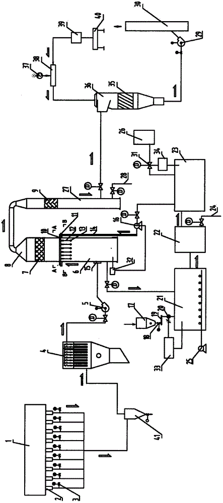
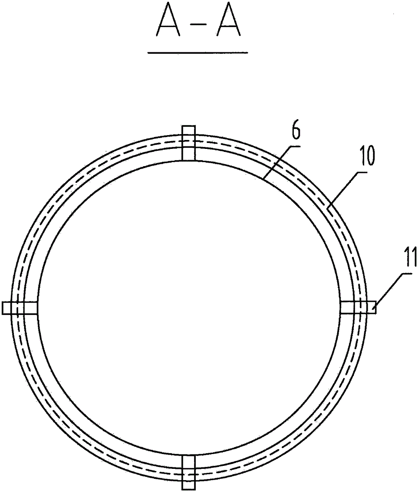
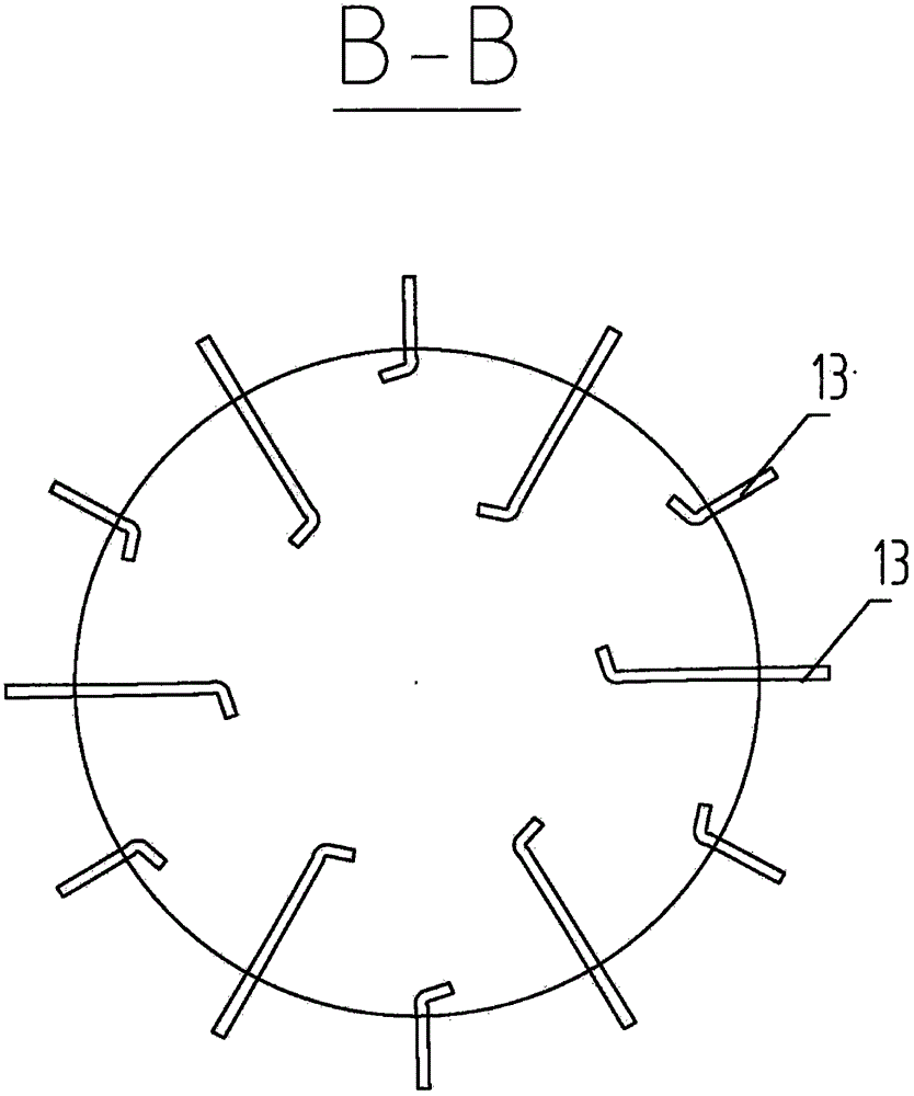
[0025] like figure 1 , figure 2 , image 3 As shown, the present invention is a sintering machine flue gas desulfurization and denitrification equipment, including a sintering machine 1, a bellows 2, a cyclone dust collector 41, a bag filter 4, a booster fan 5, a desulfurization tower 6, a dehumidification and purification tower 9, and an SCR reaction device 36, fan 29, chimney 30, characterized in that: the sintering machine 1 is sequentially connected to the wind box 2, the cyclone dust collector 41, the bag filter 4, the booster fan 5, the desulfurization tower 6, the dehumidification and purification tower 9, and the SCR reactor 36. Fan 29, chimney 30, an electric regulating valve 3 is connected between the bellows 2 and the cyclone dust collector 41, the outlet of the fan 5 is connected to the air inlet 15 of the desulfurization tower, and the side wall of the ...


PUM


Abstract

The invention discloses flue gas desulfurization and denitrification equipment of a sintering machine. The flue gas desulfurization and denitrification equipment comprises the sintering machine, an air box, a cyclone dust collector, a bag-type dust collector, a booster fan, a desulfurizing tower, a dehumidification purifying tower, an SCR reactor, a draught fan and a chimney and is characterized in that the sintering machine is sequentially connected with the air box, the cyclone dust collector, the bag-type dust collector, the booster fan, the desulfurizing tower, the dehumidification purifying tower, the SCR reactor, the draught fan and the chimney; an electric control valve is connected between the air box and the cyclone dust collector; an outlet of the draught fan is connected with an air inlet of the desulfurizing tower; a pH detection controller is arranged on the side wall of the lower part of the air inlet of the desulfurizing tower and is connected with a desulfurizing pump through a control cable; the lower part of the air inlet of the desulfurizing tower is connected with an aeration replacement reaction tank through a pipeline; the aeration replacement reaction tank is connected with a sedimentation tank; and a Roots blower is arranged on one side of the aeration replacement reaction tank. The flue gas desulfurization and denitrification equipment has the following advantages that the desulfurization efficiency is high, the investment operating cost is low, the maintenance is easy, the occupied area is small, and the service life of the equipment is long.

Description

technical field [0001] The invention relates to a flue gas desulfurization and denitrification equipment, in particular to a sintering machine flue gas desulfurization and denitrification equipment. Background technique [0002] At present, during the 1200°C high-temperature firing process of the coke powder and coal powder used in sintering production, the sulfur and nitrogen in the raw materials undergo a chemical reaction to form SO 2 , NOx enters the sintering flue gas, and the SO emitted from the sintering machine 2 , NOx accounted for domestic SO 2 , A large part of the total NOx emission is the emission source second only to thermal power plants. According to the analysis of sintering flue gas, it has the following characteristics: [0003] (1) The concentration of SO2 in the sintering flue gas changes very quickly and the concentration fluctuates greatly; [0004] (2) The temperature of flue gas emitted from sintering usually fluctuates between 100°C and 150°C; ...

Claims


Application Information

Patent Timeline
Patent Type & Authority Applications(China)
IPC IPC(8): F27D17/00
Inventor 戴顺国
Owner WUXI SHENGJIE ENVIRONMENTAL PROTECTION TECHCO LTD
Learn More