
Desulphurization and denitration apparatus for flue gas of coal-fired boiler

A coal-fired boiler, desulfurization and denitrification technology, applied in the direction of combined devices, climate change adaptation, climate sustainability, etc., can solve environmental pollution, dust concentration, flue gas oxygen content, high moisture content, heavy metal concentration, failure to meet emission standards, etc. problems, to achieve the effect of reducing emission concentration, high desulfurization efficiency, and small footprint

Inactive Publication Date: 2016-11-23
WUXI SHENGJIE ENVIRONMENTAL PROTECTION TECHCO LTD
View PDF0 Cites 0 Cited by
  • Summary
  • Abstract
  • Description
  • Claims
  • Application Information

AI Technical Summary

Problems solved by technology

[0008] To sum up, the temperature of flue gas emitted by coal-fired boilers is mostly between 120 and 160 °C, and the flue gas environment conditions are relatively harsh, such as high dust concentration, high oxygen content of flue gas, and low moisture content. high concentration of heavy metals, etc., in the case of using high-sulfur coal, the flue gas SO 2 The emission concentration reaches 5000~6000mg / Nm 3 , only the first-stage cycle dry desulfurization method can not achieve SO 2 Emission concentration 3 In addition, the NOx emission concentration reaches 600-800g / Nm 3 , causing serious pollution to the environment

Method used


Image

  • Desulphurization and denitration apparatus for flue gas of coal-fired boiler
  • Desulphurization and denitration apparatus for flue gas of coal-fired boiler
  • Desulphurization and denitration apparatus for flue gas of coal-fired boiler

Examples


Embodiment Construction

[0025] The present invention will be further described below in conjunction with the accompanying drawings.

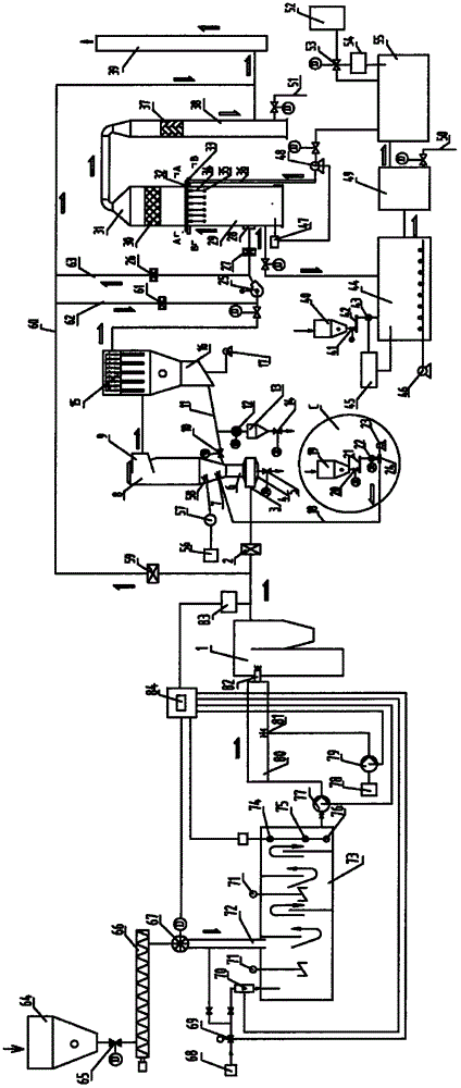
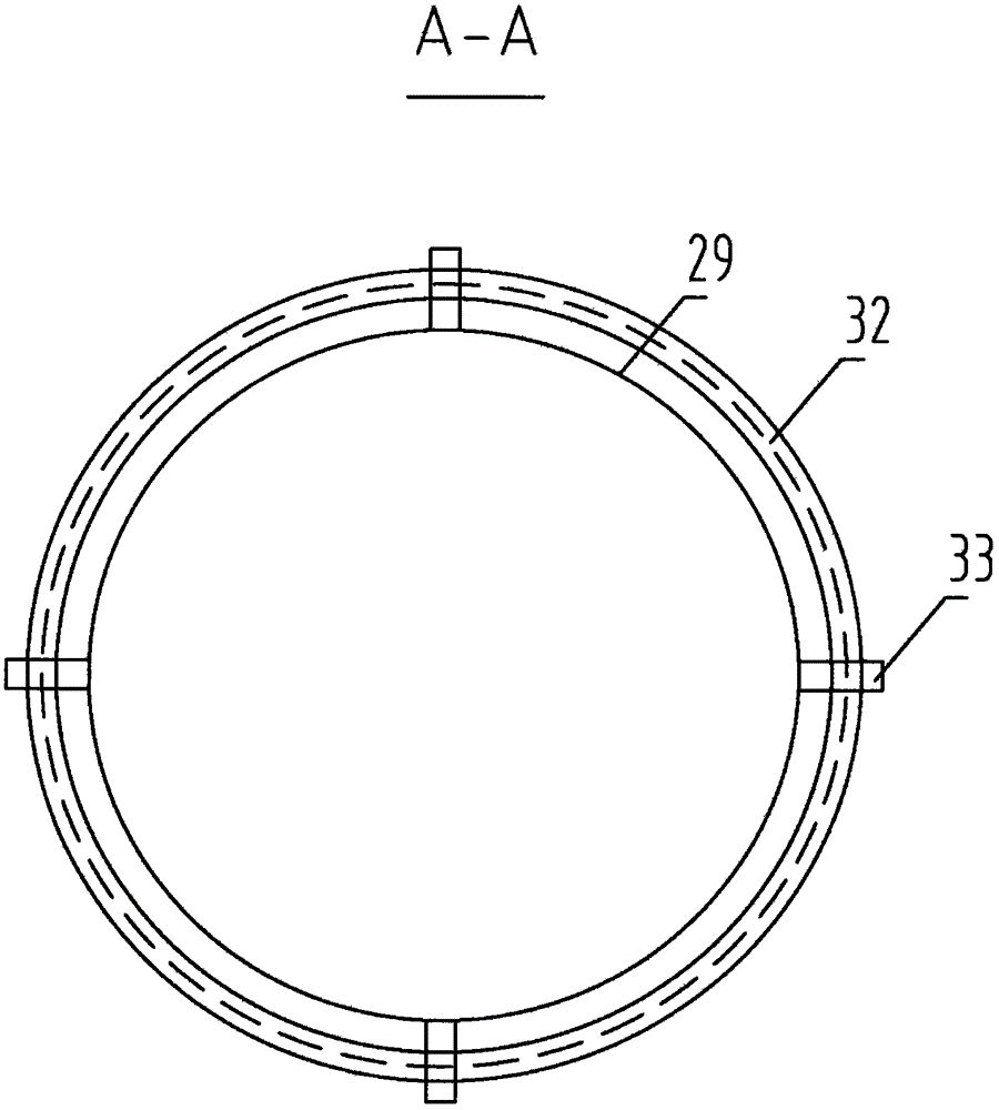
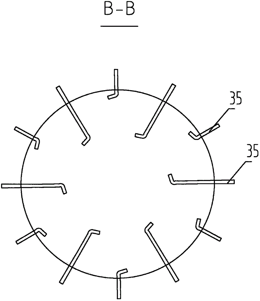
[0026] Such as figure 1 , figure 2 , image 3 , Figure 4 As shown, the present invention is a coal-fired boiler flue gas desulfurization and denitrification device, including a coal-fired boiler 1, a flue gas online monitoring and control device 83, an electric air inlet valve 2, a reaction tower 8, a bag filter 15, a fan 25, a desulfurization Tower 29, dehumidification and purification tower 30, and chimney 39, characterized in that: the coal-fired boiler 1 is sequentially connected to the flue gas online monitoring and control device 83, the electric air inlet valve 2, the reaction tower 8, the bag filter 15, the fan 25, the desulfurization Tower 29, dehumidification and purification tower 30, chimney 39, a bypass pipe 60 is connected between the coal-fired boiler 1 and the inlet of the electric air inlet valve 2, the bypass pipe 60 is connected with the inlet o...


PUM


Abstract

The invention provides a desulphurization and denitration apparatus for flue gas of a coal-fired boiler. The desulphurization and denitration apparatus comprises the coal-fired boiler, a flue-gas on-line monitoring and controlling device, an electric air inlet valve, a reaction tower, a bag-type dust collector, a fan, a desulfurization tower, a dehumidifying and purifying tower and a chimney. The apparatus is characterized in that the coal-fired boiler is successively connected with the flue-gas on-line monitoring and controlling device, the electric air inlet valve, the reaction tower, the bag-type dust collector, the fan, the desulfurization tower, the dehumidifying and purifying tower and the chimney; a bypass pipeline is arranged between and connected with the coal-fired boiler and the electric air inlet valve; the bypass pipeline is connected with the inlet of the chimney; a by-passing valve is arranged on the bypass pipeline; the outlet of electric air inlet valve is connected with the air inlet of the reaction tower; the lower part of the air inlet of the reaction tower is connected with a taper ash collecting groove; the taper ash collecting groove is connected with an electric cindervalve; and the upper part of the air inlet of the reaction tower is connected with a throat pipe. The desulphurization and denitration apparatus can remove pollutants like SO2 gas and nitrogen oxides in the flue gas of the coal-fired boiler, enables flue gas to be discharged after reaching the standard and avoids pollution to environment.

Description

technical field [0001] The invention relates to a coal-fired boiler flue gas desulfurization and denitrification device, specifically for purifying the flue gas produced by the coal-fired boiler, and belongs to the technical field of environmental protection. Background technique [0002] At present, the pulverized coal used in coal-fired boilers contains sulfur. During the high-temperature firing process at 1200°C to 1500°C, the sulfur in the raw materials reacts chemically to form SO 2 Into flue gas, SO emitted from coal-fired boilers 2 accounted for domestic SO 2 A large part of the total emissions, according to the analysis of the flue gas of coal-fired boilers, has the following characteristics: [0003] (1) The concentration of SO2 in the flue gas of coal-fired boilers changes very quickly and the concentration fluctuates greatly; [0004] (2) The temperature of flue gas emitted by coal-fired boilers usually fluctuates between 120°C and 160°C; [0005] (3) The dust...

Claims


Application Information

Patent Timeline
IPC IPC(8): B01D53/75B01D53/79B01D53/56B01D53/50B01D53/78B01D53/83B01D46/02B01D50/00B01D53/68F23J15/02
CPCY02A50/2351
Inventor 戴顺国
Owner WUXI SHENGJIE ENVIRONMENTAL PROTECTION TECHCO LTD
Learn More