Electrifying wire-switching device and running method

A linear and switching signal technology, applied in the direction of measuring devices, measuring device shells, measuring electrical variables, etc., can solve the problems of high labor intensity, low test efficiency, and long time consumption of test personnel, so as to improve test efficiency and safety, simplify Experimental operating procedures, the effect of reducing labor intensity

Active Publication Date: 2016-11-23
GUILIN POWER CAPACITOR
View PDF18 Cites 1 Cited by
  • Summary
  • Abstract
  • Description
  • Claims
  • Application Information

AI Technical Summary

Problems solved by technology

Since the test voltage used in the coupling capacitor test can reach hundreds of kilovolts, a sufficient safety distance must be ensured between the control room and the product test area. During the entire test process, testers need to frequently enter and exit the control room and test area , split test power supply, voltage up and down, time-consuming
Especially in the batch test, the test efficiency is low, the labor intensity of the test personnel is high, the safety is reduced, and the loss of test equipment is large

Method used


Image

  • Electrifying wire-switching device and running method
  • Electrifying wire-switching device and running method
  • Electrifying wire-switching device and running method

Examples


Embodiment 1

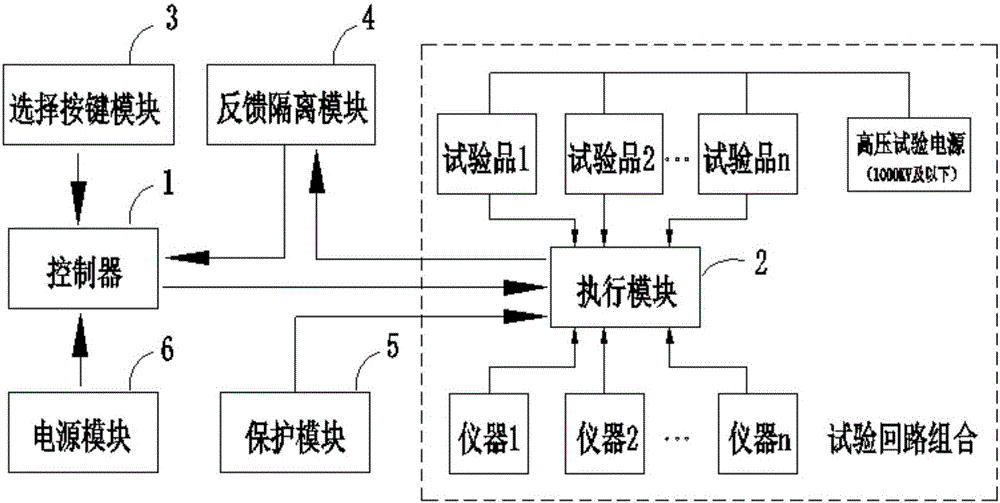
[0043] Such as figure 1 As shown, a live wire changing device includes:

[0044] a controller 1, configured to generate a line change control signal;

[0045] The execution module 2 is used to connect one of the multiple test circuits, and is also used to switch on the selected test circuit for testing according to the line change control signal, and delay disconnecting the last test circuit connected to it.

[0046] Preferably, it also includes a selection button module 3, the selection button module 3 is used to generate a switch signal according to the touch press, and transmit the switch signal to the controller 1, and the controller 1 generates a line change control signal according to the switch signal; When the selection button module 3 is pressed by two touch points at the same time, two switching signals are correspondingly generated, and the controller 1 generates a line change control signal according to the switching signal of the last touch-pressed switching sign...

Embodiment 2

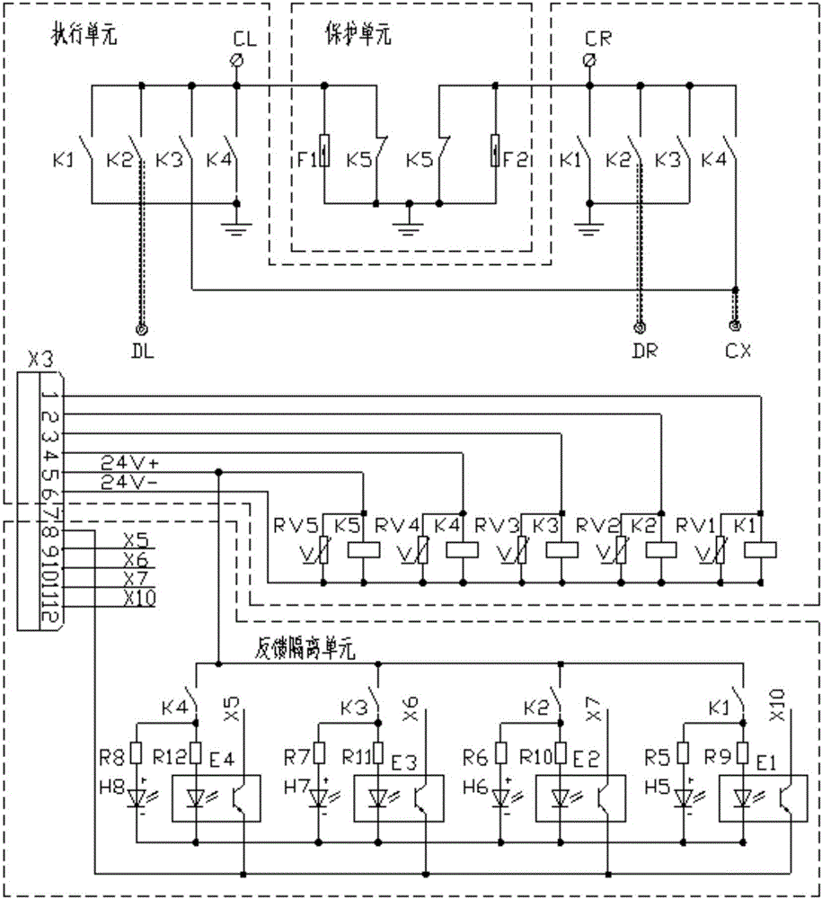
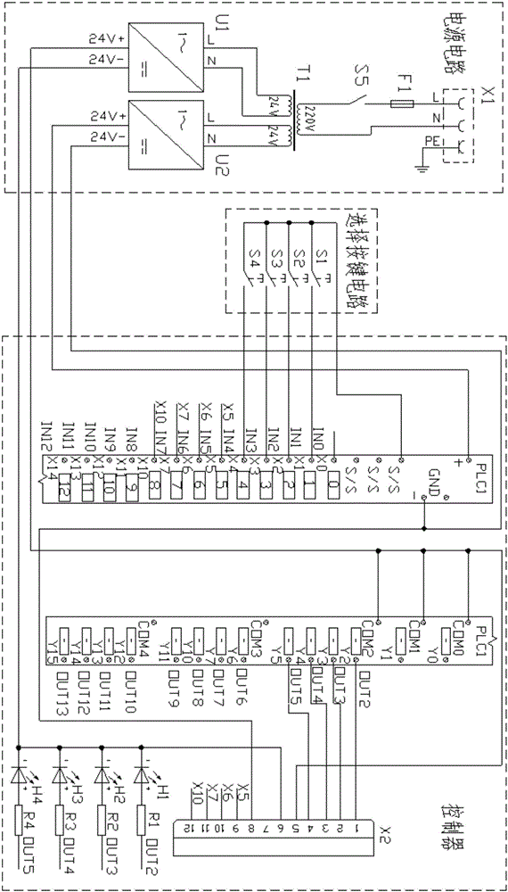
[0057] Such as Figures 1 to 5 As shown, the controller 1 takes a programmable logic controller (PLC) as the core, and the output ports Y2, Y3, Y4, and Y5 of the PLC respectively control the coils of the four relays K1, K2, K3, and K4 of the execution module 2, The four unlocked buttons S1, S2, S3, and S4 of the selection button module 3 are switch buttons for withstand voltage test, partial discharge test, CL capacitance measurement, and CR capacitance measurement, and their contacts are respectively connected to the input ports X1 and X2 of the PLC. , X3, and X4 are connected; PLC input ports X5, X6, X7, and X10 respectively receive the status signals fed back by the isolation feedback module 4 for fault detection; indicator lights H1 to H8 are used for working status indication. The coil of relay K5 is directly connected to the 24V power supply as power-off protection.

[0058] By programming the PLC, it can complete the following functions: In any state, press any switch ...


PUM


Abstract

The invention relates to an electrifying wire-switching device and a running method. The device comprises a controller and an executing module, wherein the controller is used for generating a wire-switching control signal and the executing module is used for connecting a test loop of a plurality of test loops, switching the connecting to the selected another test loop for test according to the wire-switching control signal, and delaying the disconnecting of the previous test loop which is connected. Compared with the prior art, the electrifying wire-switching device has the advantages that the test wiring is switched under the electrifying condition; no discharging phenomenon happens in a switching process; the test operation program is simplified; the test efficiency and safety are effectively increased; the labor intensity of the tester and the loss of test equipment are reduced.

Description

technical field [0001] The invention relates to the technical field of high-voltage electrical testing, in particular to a live wire changing device and an operation method. Background technique [0002] Among the routine test items for coupling capacitors required by national standards, there are tests such as power frequency withstand voltage test, partial discharge test, initial capacitance dielectric loss test, and capacitor dielectric loss retest. The common feature of this type of test is that the high-voltage terminal (high-voltage electrode) of the test object is always connected to the high-voltage end of the test power supply, and the test items are completed only by changing the connection between the low-voltage terminal (low-voltage electrode) of the test object and different test instruments. transform. [0003] During the test, due to the high test voltage, under the test voltage of tens of kilovolts or even hundreds of kilovolts, if the connection line betwe...

Claims


Application Information

Patent Timeline
Patent Type & Authority Applications(China)
IPC IPC(8): G01R1/04
CPCG01R1/0416
Inventor 宋守龙李必春梁琮顾风彪王增文谭彦民李小燕莫华明肖晓红刘雁兵
Owner GUILIN POWER CAPACITOR
Why Eureka
Try Eureka