Medium-voltage electrical penetrating member ceramic component

An electrical penetration, medium-voltage technology, applied in nuclear power generation, greenhouse gas reduction, climate sustainability, etc., can solve the problems of poor radiation resistance, corrosion and high temperature and high pressure capability, short service life, and poor structural strength, etc. To achieve the effect of strong insulation performance and pressure bearing capacity, good seismic buffering effect and high connection strength

Pending Publication Date: 2016-11-23
江苏华光电缆电器有限公司
View PDF13 Cites 3 Cited by
  • Summary
  • Abstract
  • Description
  • Claims
  • Application Information

AI Technical Summary

Problems solved by technology

Since electrical penetrations are used for the electrical connection of the internal and external equipment of the reactor, organic materials are usually difficult to meet the special requirements of the reactor for radiation resistance, high temperature resistance, and long life, which makes the existing electrical penetrations have the following disadvantages: due to their structure Poor strength, easy deformation of cylinder during installation; poor pressure bearing capacity, poor resistance to radiation, corrosion and high temperature and high pressure, easy aging, short service life; poor sealing, easy to leak; poor stability in continuous operation
The above solution solves the problem of poor sealing of existing electrical penetrations to a certain extent, but this solution still cannot fundamentally solve the problems of poor structural strength, poor pressure bearing capacity, easy aging, short service life and poor stability

Method used


Image

  • Medium-voltage electrical penetrating member ceramic component
  • Medium-voltage electrical penetrating member ceramic component
  • Medium-voltage electrical penetrating member ceramic component

Examples


Embodiment Construction

[0020] The present invention will be described in further detail below in conjunction with the accompanying drawings and specific embodiments.

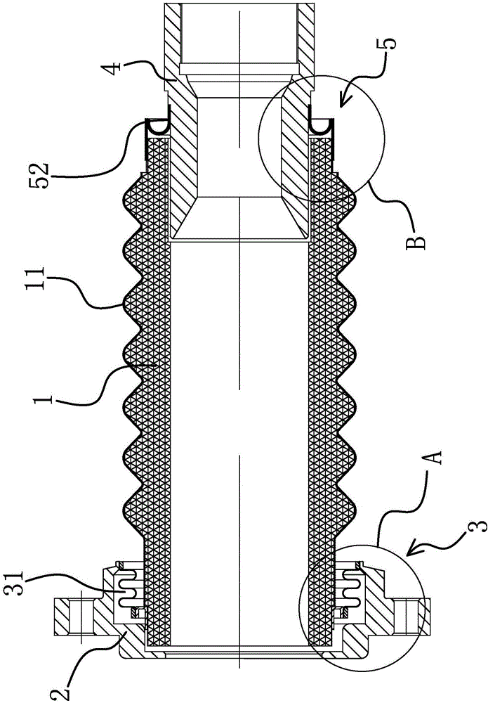
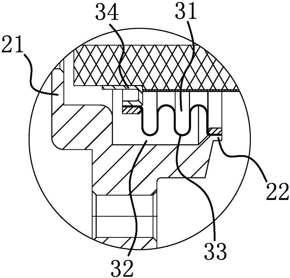
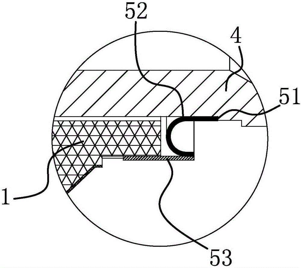
[0021] Such as Figure 1-3 As shown, the ceramic assembly of the medium-voltage electrical penetration part includes a cylindrical medium-voltage magnetic part 1, one end of the medium-voltage magnetic part 1 is provided with a magnetic part flange 2, and the circumferential inner side of the magnetic part flange 2 is connected to the medium-voltage magnetic part. There is a buffer connection structure 3 between the outer side of the magnetic part 1 and the flange 2 of the magnetic part and the medium voltage magnetic part 1. The other end of the medium voltage magnetic part 1 is inserted with a magnetic part holder 4, and the magnetic part is clamped The seat 4 is fixedly arranged at the end of the medium-voltage magnetic part 1 through the positioning structure 5, that is, the buffer connection structure 3 makes the magnetic part fl...


PUM


Abstract

The invention belongs to the technical field of nuclear reactor electrical penetrating member equipment, particularly relates to a medium-voltage electrical penetrating member ceramic component and solves the problem that existing electrical penetrating members are low in load bearing capability. The medium-voltage electrical penetrating member ceramic component comprises a cylindrical medium-voltage magnetic member. The medium-voltage electrical penetrating member ceramic component is characterized in that a magnetic member flange sleeves one end of the medium-voltage magnetic member, a buffering connection mechanism enabling the magnetic member flange and the medium-voltage magnetic member is arranged between the peripheral inner side of the magnetic member flange and the peripheral outer side of the same, and a magnetic member clamping seat is inserted at the other end of the medium-voltage magnetic member and fixedly arranged at the end of the medium-voltage magnetic member through a positioning structure. The medium-voltage electrical penetrating member ceramic component has the advantages that the component is simple in structure, parts are high in connecting strength, and the component is good in sealing performance, high in insulativity and pressure bearing capability, good in shock-proof and buffering effect, resistant to radiation and aging and long in service life.

Description

technical field [0001] The invention belongs to the technical field of nuclear reactor electrical penetration equipment, and in particular relates to a medium-voltage electrical penetration ceramic assembly. Background technique [0002] In order to ensure the transmission of power supply, control, protection, nuclear measurement, lighting, instrumentation, communication and other signals of the electrical equipment in the reactor containment, the cables are required to run through the special airtight containment, and the electrical penetrations are designed to realize this function. A device for connecting cables inside and outside the containment. Since electrical penetrations are used for the electrical connection of the internal and external equipment of the reactor, organic materials are usually difficult to meet the special requirements of the reactor for radiation resistance, high temperature resistance, and long life, which makes the existing electrical penetrations...

Claims


Application Information

Patent Timeline
Patent Type & Authority Applications(China)
IPC IPC(8): G21C13/036
CPCG21C13/036Y02E30/30
Inventor 孙小华王剑韦庆成甄全王斌李鑫杨冬冬沈强鲍寅华
Owner 江苏华光电缆电器有限公司
Why Eureka
Try Eureka