LNG centralized gasification comprehensive utilization system and method

A technology of comprehensive utilization and power generation system, applied in the field of LNG centralized gasification comprehensive utilization system, can solve the problem that the amount of gas and the type of valve used cannot meet the cold source demand of the cold chain industry group, the radius of cold energy transmission is limited, and the cold energy is restricted. Use and other problems to achieve the effect of solving the problem of energy transformation and upgrading, continuous and stable cooling energy output, and preventing energy loss

Active Publication Date: 2019-07-02
重庆齐祥新能源投资有限公司
View PDF4 Cites 0 Cited by
  • Summary
  • Abstract
  • Description
  • Claims
  • Application Information

AI Technical Summary

Problems solved by technology

[0004] 1. The wharf is an independent project. It is often built in a relatively remote area or an area suitable for docking ships. It does not depend on the layout of the city and its industrial park. Once it is completed, even if there is cold energy, it is impossible to form a cold chain industry. industry group
[0005] 2. The effective transmission radius of the cold energy generated in LNG gasification is within three kilometers. If the cold chain industry group cannot be formed within three kilometers around the completed wharf, its cold energy utilization will be restricted. The cold energy of Shenzhen greenhouses Utilization is like this, the cold energy facilities that have already been built cannot be fully utilized
[0006] 3. If the wharf only supplies gas to a certain type of specific users, and the type of gas is single, the continuity of gasification will be restricted by the peak production of gas units; The layout of the chain industry group cannot make full use of cold energy; at the same time, it is often difficult to realize long-distance pipeline network investment and construction and cross-regional coordination. Deeply drained into seawater, such is the case at Shenzhen Greenhouse Receiving Station
[0008] 1. When the LNG satellite station project was established, there was no supporting industrial group for the cold chain industry. The site is surrounded by residential areas or other types of industrial areas. It is possible to form a small-scale freezer, but it is impossible to form a cold chain industry group, and the small freezer And because of the lack of professional operation, it is very difficult to operate
[0009] 2. Due to the limitation of the cold energy transmission radius, it is very difficult to satisfy the project within a radius of three kilometers even if the project establishment of the cold chain industry group is reconsidered
[0010] 3. Only the gas consumption and gas consumption category of a certain LNG satellite station cannot meet the cold source demand of a cold chain industry group
[0011] Because of the above reasons, in practice, the utilization rate of cold energy produced in LNG gasification is very low, and from the perspective of national energy conservation, emission reduction, and energy upgrading, the large-scale application of natural gas is the best choice at present. Under such a general background, if a local area, especially an area without a national main network gas supply for a long time, can provide a solution to effectively utilize the cold energy generated during the LNG gasification process, it will not only realize energy upgrading , energy saving and emission reduction can also give birth to the development of the cold chain industry, which will have extremely high economic and social value

Method used


Image

  • LNG centralized gasification comprehensive utilization system and method
  • LNG centralized gasification comprehensive utilization system and method
  • LNG centralized gasification comprehensive utilization system and method

Examples


Embodiment Construction

[0036] The preferred embodiments of the present invention will be described in detail below in conjunction with the accompanying drawings, so that the advantages and features of the present invention can be more easily understood by those skilled in the art, so as to define the protection scope of the present invention more clearly.

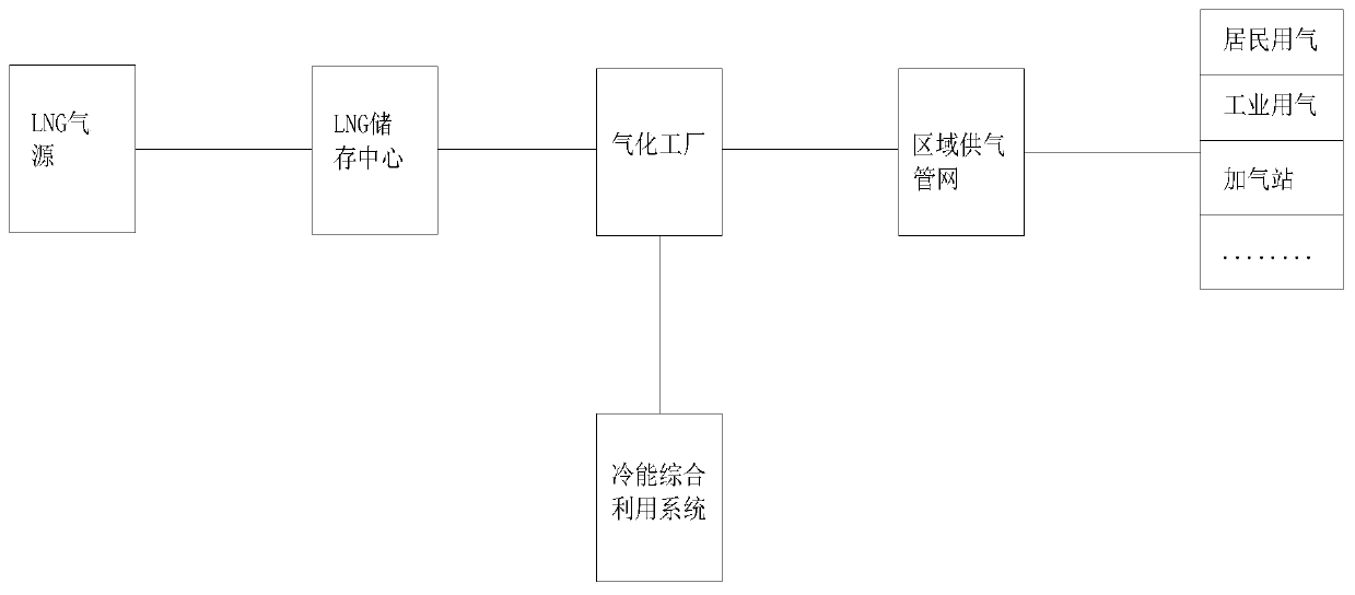
[0037] like figure 1Shown: A comprehensive utilization system of LNG centralized gasification, including an LNG storage center, which transports LNG to the LNG storage center through tankers, and the LNG in the LNG storage center is gasified by the gasification plant and then connected to the area The gas supply pipeline network, the terminal of the gas supply pipeline network in this area is connected to the residential gas terminal, industrial gas terminal and gas filling station, etc., and the gasification plant is also connected to the cold energy comprehensive utilization system;

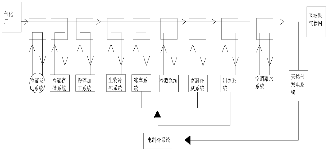
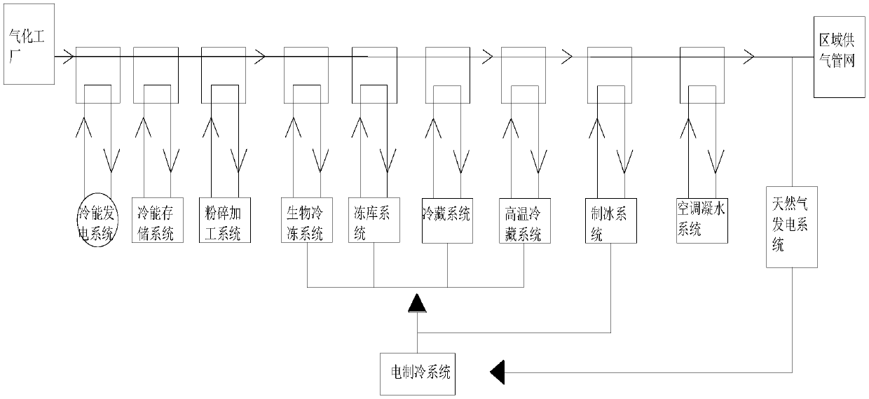
[0038] like figure 2 As shown: the cold energy comprehensi...


PUM


Abstract

The invention provides an LNG concentrated gasification and comprehensive utilization system and method. The system comprises an LNG storage center. Liquefied natural gas in the LNG storage center is switched into an area gas supply pipe network after being gasified through a gasification plant. The terminal of the area gas supply pipe network is connected with various categories of area gas utilization users. The gasification plant is further connected with a cold energy comprehensive utilization system. The cold energy comprehensive utilization system comprises a main heat exchange system and exchanges cold energy with the gasification plant through the main heat exchange system. A smashing processing system, a biological refrigeration system, a freezer system and a high-temperature cold storage system are sequentially connected to the main heat exchange system from low temperature to high temperature. According to the method, by starting and stopping all the systems, the optimal utilization state is achieved, and the green and sustainable application mode is truly achieved.

Description

technical field [0001] The invention relates to the technical field of LNG development and utilization, in particular to an LNG centralized gasification comprehensive utilization system and method. Background technique [0002] Under a standard atmospheric pressure, the cold energy contained in LNG is about 840Kj / Kg, that is, each kilogram of LNG has 840 kilojoules of cold energy; according to this calculation, each ton of LNG contains 230KWh of cold energy. LNG must be gasified from a liquid state at -162°C to a gaseous state at 18°C ​​before it can be used as natural gas. In this gasification process, cold energy must be released, that is to say, if this cold energy can be utilized, this cold energy is a by-product of LNG. In LNG production sites, turning gaseous natural gas into LNG requires about 0.3 yuan of electricity per cubic meter, and 435 yuan of electricity is stored in one ton of LNG. [0003] In the prior art, there is also the utilization of the cold source g...

Claims


Application Information

Patent Timeline
Patent Type & Authority Patents(China)
IPC IPC(8): F17C7/04F25J1/02F25D3/02F25B21/00F28D20/00
CPCF17C7/04F25B21/00F25D3/02F25J1/02F28D20/00Y02B30/00Y02E60/14
Inventor 黄唯琦黄瀚
Owner 重庆齐祥新能源投资有限公司
Why Eureka
Try Eureka