Intelligent pulse combustion system

A pulse combustion and intelligent technology, applied in the direction of burner, combustion method, combustion type, etc., can solve problems such as poor control effect, achieve convenient operation and maintenance, reduce system cost, and increase reliability

Inactive Publication Date: 2016-12-07
钟海胜
4 Cites 8 Cited by

AI-Extracted Technical Summary

Problems solved by technology

[0003] At present, continuous combustion control forms such as proportional control and double cross limit control are generally used in China, but they are often restricted by the key link of fuel quantity measurement and adjustment, an...

Method used

[0029] The pulse controller 12 controls the dynamic adjustment of the gas solenoid valve 4 and the air solenoid valve 8 switches to realize switching and duration of more than two combustion states. The temperature controller 15 is connected with the temperature sensor 16 in the industrial furnace 10 to detect the temperature value in the industrial furnace 10 . Calculate the deviatio...

Abstract

The invention discloses an intelligent pulse combustion system. The intelligent pulse combustion system comprises a gas pipeline, a combustion assisting air pipeline, a combustor and a control system; the gas pipeline introduces gas into the combustor; the combustion assisting air pipeline introduces air into the combustor; nd the control system controls coordinated work of the gas pipeline, the combustion assisting air pipeline and the combustor to realize intelligent pulse combustion control. The intelligent pulse combustion system realizes intelligent pulse combustion control through controlling the combustion state switching and the combustion lasting time of the combustor by the control system according to a deviated value between a detected industrial furnace actual temperature and a preset temperature. The intelligent pulse combustion system can realize precise control of a combustion atmosphere, improves the heat transfer efficiency, largely reduces the energy consumption, needs no online adjustment, can increase the burner load adjusting ratio, is simple and reliable, is low in manufacturing cost, and can reduce generation of NOx.

Application Domain

Technology Topic

Image

  • Intelligent pulse combustion system
  • Intelligent pulse combustion system
  • Intelligent pulse combustion system

Examples

  • Experimental program(1)

Example Embodiment

[0022] The principle and specific embodiments of the present invention will be further described below in conjunction with the accompanying drawings.
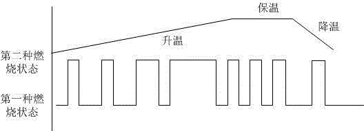
[0023] Pulse combustion uses an intermittent combustion method to achieve temperature control in the furnace. The fuel flow can be pre-set by pressure adjustment. Once the burner is working, according to the heating process curve requirements, when the temperature needs to be raised, the target temperature is set, the second combustion state When the time is longer, the intermittent time is reduced; when the target temperature is close, the time of the second burning state is reduced, and the time of the first burning state is lengthened, and it enters the heat preservation state. When the temperature needs to be lowered, all switch to the first burning state, such as figure 1.
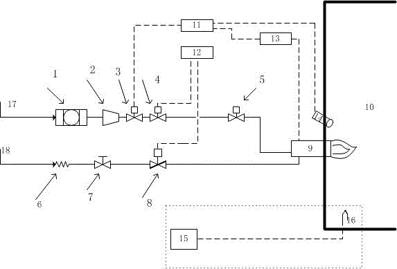
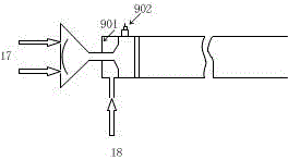
[0024] Intelligent pulse combustion system, including gas pipeline 17, combustion air pipeline 18, burner 9, temperature sensor 16 and control system. Gas pipeline 17 and combustion air pipeline 18 are connected to burner 9, temperature sensor 16 is taken in industry In the furnace 10, the control system serves as the central control unit and is the core of the entire combustion system, which controls the gas pipeline 17, air pipeline 18 and burner 9 to work in coordination.
[0025] The inlet of the combustion-supporting air pipeline 18 is provided with a bellows 6, a manual regulating valve 7 and an air solenoid valve 8. After air is introduced, the bellows 6 maintains the air at a stable pressure level, adjusts the manual regulating valve 7, and opens the air solenoid valve 8 and gas solenoid valve 4, air and gas reach the preset fuel-air ratio and pass into the burner 9.
[0026] The inlet of the gas pipeline 17 is provided with a filter 1, a pressure reducing and stabilizing valve 2, an emergency shut-off valve 3, a gas solenoid valve 4 and a gas regulating valve 5. After the gas is passed in, the gas is filtered through the filter 1 in sequence and passed through all The pressure reducing and stabilizing valve 2 adjusts the gas flow and maintains a stable pressure, and opens the emergency shut-off valve 3 and the gas solenoid valve 4. The opening of the gas regulating valve 5 is used to adjust the amount of gas. The air is first introduced for a period of time and then controlled by pulse The gas solenoid valve 4 is controlled by the device 12 to open the gas into the burner 9.
[0027] The control system includes an ignition controller 11, an ignition transformer 13, a pulse controller 12 and a temperature controller 15.
[0028] When the igniter 902 is ignited, the ignition controller 11 controls the ignition transformer 13 to output a high-frequency voltage to produce sparks in the first combustion state, which is used to ignite the gas and produce two or more different combustion states. The flame monitor 14 provided by the burner 9 Check whether the switching of the combustion state in the burner 9 is successful. If the ignition fails, the information will be fed back to the ignition controller 11, and the ignition controller 11 will close the emergency shut-off valve 3 and send out a red alarm at the same time. figure 2. Considering that industrial furnaces are generally far away from the control room, two ignition methods are designed, remote and on-site, which can be ignited and extinguished through the operator station screen in the control room, or ignited through the on-site operation box button.
[0029] The pulse controller 12 controls the on-off dynamic adjustment of the gas solenoid valve 4 and the air solenoid valve 8 to realize the switching and duration of more than two combustion states. The temperature controller 15 is connected to the temperature sensor 16 in the industrial furnace 10 to detect the temperature value in the industrial furnace 10. Calculate the deviation value for the preset temperature and the detected temperature in the industrial furnace 10, and use the dynamic detection result of the deviation value as the basis for the pulse controller 12 to control the combustion sequence and combustion time of the burner 9 to achieve intelligent pulse combustion control. Accurate temperature control meets the process effect.
[0030] The pulse controller outputs a switching signal according to the deviation value to control the switching frequency and duration of the air solenoid valve and the gas solenoid valve, that is, control the switching frequency and duration of the two combustion states, thereby controlling the temperature of the corresponding heating section. When the switch quantity signal is "0", the gas regulating valve is opened for a small degree (for example, the opening degree is preset to 10%) for combustion in the first combustion state. When the switch quantity signal is "1" and the burner has a small fire, the gas regulating valve opens a large opening (for example: the preset opening is 90%), and the switch quantity is controlled according to the temperature deviation value, which can reach the pulse Combustion control can also save fuel and fully burn to achieve the best combustion state.
[0031] image 3 In the burner 9, there is a mixing box 901 and an igniter 902. The mixing box 901 is used to place the mixed gas and fully mix the gas and air. All the burners are not ignited at the same time, but are ignited in sequence according to a certain time sequence t. It is easy to achieve the best combustion state.
[0032] The gas and air enter the mixing box in the combustor to fully mix. Once the combustor works, it is at full load. This system does not adjust the fuel input in a certain area, but adjusts each combustor in a given area. Frequency and duration of ignition. The input quantity n of the burner is given in advance, the branch is around the industrial furnace, and each burner opens and closes at a frequency proportional to the given opening and heat demand, see Figure 4. Modern industrial furnaces require high temperature control accuracy and temperature uniformity (the difference between the actual temperature and the set temperature should not exceed ±5℃, and the temperature difference between two adjacent areas of the same heating section cannot exceed ±10℃). The number of temperature sensors set in the furnace is given in advance The number of burners is consistent with the number of burners. During the heating process, the opening of the gas regulating valve is increased and all switch to the second combustion state. When the detected furnace temperature is less than 5°C, some burners will switch in advance It is the first combustion state, keeping the temperature in the furnace stable; if the measured temperature is 5°C higher than the set temperature, all burners will switch to the first combustion state.
[0033] The control system mainly completes communication, temperature control, data collection, important logic control, etc., such as cut-off, normal ignition/fault, etc. The operator can operate and monitor the combustion conditions of the industrial furnace through the screen, such as ignition, flameout operation, monitoring the actual temperature control in the furnace, historical data query, print report, alarm confirmation and query, etc.
[0034] The specific embodiments of the present invention are described above with reference to the accompanying drawings. The specific structures and processes shown in the foregoing specific embodiments are only exemplary and not restrictive, and those of ordinary skill in the art to which the present invention belongs should understand.

PUM

no PUM

Description & Claims & Application Information

We can also present the details of the Description, Claims and Application information to help users get a comprehensive understanding of the technical details of the patent, such as background art, summary of invention, brief description of drawings, description of embodiments, and other original content. On the other hand, users can also determine the specific scope of protection of the technology through the list of claims; as well as understand the changes in the life cycle of the technology with the presentation of the patent timeline. Login to view more.

Similar technology patents

Spray nozzle and gas turbine with same

ActiveCN104566471AImprove fire stabilityImprove combustion efficiencyContinuous combustion chamberPartially premixed combustionPower equipment
Owner:CHINA UNITED GAS TURBINE TECH CO LTD

Gas roller way kiln

Owner:青岛铸英特陶科技有限公司

Classification and recommendation of technical efficacy words

  • Reduce energy consumption
  • Improve combustion efficiency

Preparation method of high-strength hydrogel

InactiveCN103739861AThe preparation process takes a short timeReduce energy consumptionPolymer chemistryDouble network
Owner:HENAN POLYTECHNIC UNIV

Gas burner capable of adjusting gas to be self-recycling

Owner:GUANGZHOU INST OF ENERGY CONVERSION - CHINESE ACAD OF SCI

Biomass solid formed fuel anti-slagging additive and preparation method thereof

Owner:ACADEMY OF PLANNING & DESIGNING OF THE MINIST OF AGRI
Why Eureka
Try Eureka