PMU and method for achieving on-line identification and alarm of secondary synchronous oscillation

A technology of subsynchronous oscillation and precise synchronization, which is applied to measurement devices, instruments, measuring electricity and other directions, and can solve the problems of inability to accurately analyze the frequency components of subsynchronous oscillation, inability to analyze and monitor the dispatching master station, and frequency aliasing.

Active Publication Date: 2016-12-07
NARI TECH CO LTD +4
View PDF5 Cites 21 Cited by
  • Summary
  • Abstract
  • Description
  • Claims
  • Application Information

AI Technical Summary

Problems solved by technology

At this time, the sub-synchronous oscillation of the system will be regarded as an out-of-band signal and filtered out. The synchronized phasor sent by the PMU to the dispatching master station does not include the frequency component of the sub-synchronous oscillation. When the system occurs a sub-synchronous oscillation, the dispatching master station It is impossible to analyze and monitor based on the phasor data sent by the PMU
[0007] At the same time, even if the PMU does not filter the out-of-band signal, the SSO analysis by the dispatch master station has certain limitations. The dispatch master station uses synchrophasor data to perform SSO analysis. It is also a process of data sampling spectrum analysis , the sampling rate is the rate at which synchrophasors are sent from the PMU. At present, except for the North China power grid that uses 100Hz to transmit phasor data, most areas use 50Hz or even lower rates to transmit phasor data in order to reduce the burden on the dispatching master station. When the subsynchronous oscillation frequency component is greater than 1 / 2 of the phasor transmission rate, frequency aliasing will occur, so that the subsynchronous oscillation frequency component cannot be accurately analyzed

Method used


Image

  • PMU and method for achieving on-line identification and alarm of secondary synchronous oscillation
  • PMU and method for achieving on-line identification and alarm of secondary synchronous oscillation
  • PMU and method for achieving on-line identification and alarm of secondary synchronous oscillation

Examples


Embodiment Construction

[0060] It will be further described below in conjunction with the accompanying drawings and specific embodiments. The following examples are only used to illustrate the technical solutions of the present invention more clearly, but not to limit the protection scope of the present invention.

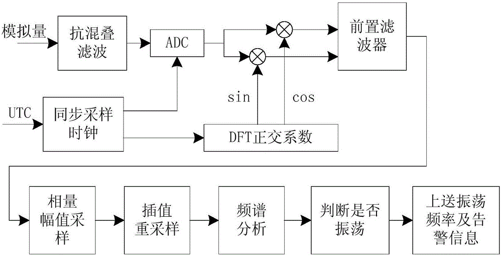
[0061] Such as figure 1 , the present invention realizes subsynchronous oscillation on-line identification alarm PMU, including anti-aliasing filter module, ADC sampling module, pre-filter module, synchronous sampling clock module, DFT orthogonal transformation module, phasor amplitude analysis and processing module and post- Send filter module;

[0062] The synchronous sampling clock module receives the external time synchronization signal, and then generates a synchronous sampling pulse signal that is precisely synchronized with the time synchronization signal, and outputs it to the ADC sampling module and the DFT orthogonal transformation module respectively;

[0063] The anti-aliasi...


PUM


Abstract

The invention discloses a PMU and a method for achieving the on-line identification and alarm of the secondary synchronous oscillation. The PMU comprises an anti-aliasing filter module, an ADC sampling module, a synchronous sampling clock module, a DFT quadrature conversion module, a front-loading filter module, a phasor amplitude analyzing and processing module, and an uploading and processing module. The method comprises the steps of accurately calculating the synchronous phasor; pre-filtering the synchronous phasor; sampling and processing the calculated amplitude of the phasor; analyzing the frequency spectrum of the phasor amplitude; identifying the secondary synchronous oscillation according to the components of the frequency spectrum of the phasor amplitude; uploading the frequency components of the secondary synchronous oscillation and the alarm information to a dispatching master station. According to the technical scheme of the invention, the on-line identification and alarm of the secondary synchronous oscillation of the power system can be completed by the PMU. Through adopting the analysis on the frequency spectrum of measured high-density phasor data, the frequency components of the secondary synchronous oscillation can be accurately calculated. Therefore, the analysis monitoring accuracy and the analysis monitoring adaptability of the secondary synchronous oscillation are improved.

Description

technical field [0001] The invention relates to the field of subsynchronous oscillation monitoring in electric power automation technology, in particular to a PMU and a method for realizing online identification and alarm of subsynchronous oscillation. Background technique [0002] With the continuous expansion of the grid scale and large-scale wind power grid-connected and sent out, in order to improve the transmission capacity and system stability, series compensation devices, high-voltage direct current (HVDC) control systems, dynamic reactive power compensation devices and other equipment have been installed in the power system. . The development of these equipment and technologies provides a new method for the power grid to improve the transmission capacity under the existing conditions, and lays the foundation for large-scale wind power grid integration and external transmission. But at the same time, it also brings certain risks to the stable operation of the power g...

Claims


Application Information

Patent Timeline
Patent Type & Authority Applications(China)
IPC IPC(8): G01R23/16G01R31/08
CPCG01R23/16G01R31/088Y02E40/70Y02E60/00Y04S10/00Y04S10/22
Inventor 张敏沈健周斌侯明国檀永彭奇殷垚刘东升
Owner NARI TECH CO LTD
Why Eureka
Try Eureka