Effect verification method for locking circuit apparatus of pressure machine

A verification method and press technology, applied in the field of verification, can solve the problems of complex operation, high cost, long time-consuming, etc., and achieve the effects of accurate and reliable analysis, short development cycle and low cost

Inactive Publication Date: 2016-12-07
谭琛
View PDF2 Cites 2 Cited by
  • Summary
  • Abstract
  • Description
  • Claims
  • Application Information

AI Technical Summary

Problems solved by technology

When developing the locking circuit device of a press, it is necessary to verify the effect of the device. In the prior art, a series of complex processes such as testing machine experiment, prototype experiment, individual production experiment, and mass production experiment are used, and a large number of processes are carried out in each link. The correction and change of the operation is not only complicated, but also time-consuming and costly

Method used


Image

  • Effect verification method for locking circuit apparatus of pressure machine
  • Effect verification method for locking circuit apparatus of pressure machine
  • Effect verification method for locking circuit apparatus of pressure machine

Examples


Embodiment 1

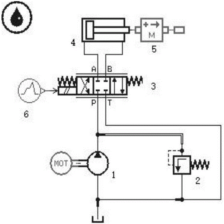
[0027] Example 1: Press locking circuit device realized by adopting the neutral function of the reversing valve

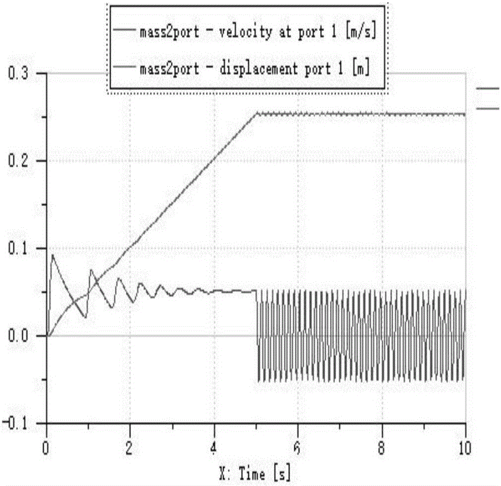
[0028] as attached figure 2 , according to the hydraulic schematic diagram, establish the AMEsim simulation model, set the parameters, the displacement of the hydraulic pump is 0.01L / rev*1500rev / min=15L / min, the set pressure of the relief valve is 150bar, and the length of the piston rod of the hydraulic cylinder is 0.3m, quality block M=1000kg, the first 5s of the electromagnetic reversing valve input signal is a constant value of 40, and the last 5s is a constant value of 0 (the same below), set the simulation time to 10s, the sampling interval is 0.01s, and run the simulation to draw the mass block M The displacement velocity curve, as attached image 3 , from the perspective of the displacement curve, the entire movement process of the hydraulic cylinder is unstable, but from the perspective of the speed curve, after 5s, that is, when the electromagnetic reve...

Embodiment 2

[0029] Example 2: Press locking circuit device with double hydraulic control check valve

[0030] Using the hydraulic component design (HCD library), firstly model the hydraulic control check valve, select the appropriate components in the HCD library, and construct the model as attached Figure 4 shown. Set the main parameters, the diameter of the control piston is 24mm, the diameter of the piston rod is 10mm, the mass of the control piston is 0.08kg, the maximum displacement is 8mm, the stiffness of the ejector rod is 2.5×10⁹N / mK, the diameter of the P1 and P2 throttle holes is 2mm, and the length is 3mm. The stiffness of the return spring of the spool is 6N / mm, the stiffness of the control piston return spring is 7N / mm, and the spring preload is 10N. Connect the hydraulic pump and the electromagnetic reversing valve. Figure 5 As shown, simulate the model of the hydraulic control check valve to verify its correctness. The input signal of the electromagnetic reversing valve...

Embodiment 3

[0032] Embodiment 3: Press locking circuit device using simple balance valve

[0033] Establish a balance valve locking circuit model. When the balance valve is opened, the weight will accelerate down. If the hydraulic cylinder rodless cavity is insufficiently filled with oil at this time, the pressure will drop. When the pressure in the rodless chamber is lower than the opening pressure of the balance valve, the balance valve will be closed, and the weight will stop falling until the pressure in the rodless chamber reaches the opening pressure of the balance valve, and then the weight will fall again, and so on, until the weight falls to the initial position. shock and noise. Therefore, a one-way throttle valve is added at the front end of the balance valve, as attached Figure 10 shown. In this way, a certain back pressure is formed in the rod cavity of the hydraulic cylinder, which effectively controls the falling speed of the weight. Run the simulation and draw the disp...


PUM


Abstract

The invention discloses an effect verification method for a locking circuit apparatus of a pressure machine. The method is characterized by comprising the steps of performing modeling and simulation: performing modeling on the locking circuit apparatus of the pressure machine and a hydraulic pump by utilizing hydraulic element design first and then forming a hydraulic simulation system comprising the locking circuit apparatus of the pressure machine; setting parameters of the locking circuit apparatus of the pressure machine; setting parameters of the hydraulic pump; running the simulation system to obtain experimental data; generating a displacement curve of a hydraulic cylinder through the experimental data; and analyzing the effect of the locking circuit apparatus of the pressure machine according to the displacement curve of the hydraulic cylinder. According to the method, the hydraulic simulation system can be quickly generated through modeling and a model assembly system; the verification process is cost-free, accurate in data and quick and convenient in data acquisition; and the analysis is accurate and reliable.

Description

technical field [0001] The invention relates to a verification method, in particular to a method for verifying the effect of a locking circuit device of a press. Background technique [0002] The function of the locking circuit of the press is to stay in the original position accurately when the actuator is not working, and the position cannot be changed due to leakage or external factors. When the locking circuit is used, it can maintain the pressure, prevent leakage, ensure the stability of the load-bearing cylinder piston, and ensure the normal operation of the machine. When developing the locking circuit device of a press, it is necessary to verify the effect of the device. In the prior art, a series of complex processes such as testing machine experiment, prototype experiment, individual production experiment, and mass production experiment are used, and a large number of processes are carried out in each link. The corrections and changes are not only complicated to op...

Claims


Application Information

Patent Timeline
Patent Type & Authority Applications(China)
IPC IPC(8): G06F17/50
CPCG06F30/17G06F30/20
Inventor 谭琛黄力
Owner 谭琛
Why Eureka
Try Eureka