Casting bottom pouring system and design method

A technology of bottom pouring and design method, which is applied in casting molding equipment, casting molds, casting mold components, etc., can solve the problems of increasing the difficulty of manufacturing, increasing the manufacturing cost of casting products, and increasing the cost of casting products, so as to reduce the filling time and stabilize the filling time. Type, fast pouring effect

Active Publication Date: 2016-12-14
贵州开磷机电装备工程有限责任公司
View PDF7 Cites 0 Cited by
  • Summary
  • Abstract
  • Description
  • Claims
  • Application Information

AI Technical Summary

Problems solved by technology

However, most casting products cannot realize bottom pouring now because in the existing casting standard process, the water inlet method of the bottom pouring process will be restricted by the shape of the casting product, and choosing other casting processes will make the technical requirements of the casting product and internal quality are not up to standard
Or to ensure the technical requirements and internal quality of casting products, special measures must be taken, which will not only increase the manufacturing cost of casting products, but also increase the difficulty of manufacturing, and relatively increase the technical requirements for equipment or people

Method used


Image

  • Casting bottom pouring system and design method
  • Casting bottom pouring system and design method
  • Casting bottom pouring system and design method

Examples


Embodiment 1

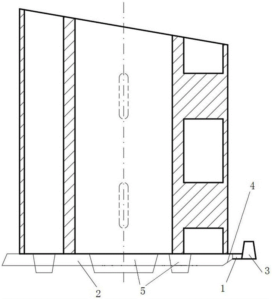
[0030] Such as image 3 and 4 As shown, it is a pouring schematic diagram of a certain stainless steel condenser tube. The structure of the casting workpiece seems not complicated, but the diameter is large (760mm), the height is high (900mm), the tube wall is thick and thin, and there are thin walls in the clamping wall. For ribs, the technological requirement is to enter water at multiple points. If the gating system is designed according to the routine, it is not only complicated, but also brings great difficulty to the shape. The pouring system designed by using the bottom pouring method of the present invention has a simple shape and can meet technological requirements.

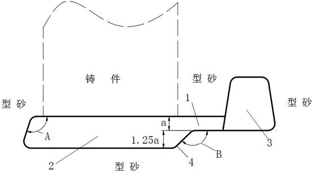
[0031] Such as Figure 4 , the water inlet 2 of the bottom pouring system is a composite type of straight water inlet and arc water inlet, which consists of 1 runner 3, 4 ingates 1, 2 straight water inlets 2, and 2 arc water inlets 2 Composition, 6 water inlets are set at the thin wall and 4 water inl...

Embodiment 2

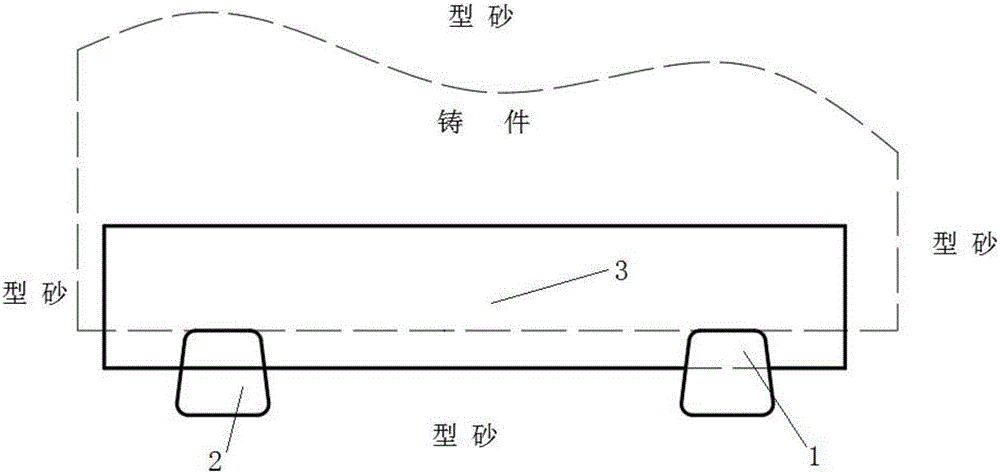
[0033] Such as Figure 5 and 6 As shown, it is a casting schematic diagram of a stainless steel pump volute. The casting has many bends and is of a volute shape. According to the conventional process, the casting will produce casting defects of different sizes on the neck of the water inlet. There are two conventional techniques, one is to open 3 to 4 ingates 1 for water intake from the volute wall; the other is to open a rain pouring system from the bottom flange. The first is simple, but not very effective; the second is complex, but also has defects.


PUM


Abstract

The invention discloses a casting bottom pouring system and design method. A water inlet channel (2) extends from the tail end of an inner pouring channel (1); a position, blocked by a sandless core head, of the casting is chosen to serve as a water inlet position of melting liquid; the quantity and the setting forms of water inlet channels (2) are determined according to the shape of the chosen position; and the shape of the cross section of the water inlet channel (2) is a trapezoid with a large lower part and a small upper part. According to the casting bottom pouring system and design method, the setting forms are not influenced by the shapes of casting products and only relate to the set position. Because multiple-point-water-inflow is achieved, mold-filling time of the melting liquid is effectively reduced and quick pouring is achieved.

Description

technical field [0001] The invention relates to a gating system for molten steel and stainless steel and a design method for the gating system, belonging to the field of casting. Background technique [0002] In the casting process, the bottom pouring process is the best choice. As long as any casting product can achieve bottom pouring, no other casting method will be selected. However, most casting products cannot realize bottom pouring now because in the existing casting standard process, the water inlet method of the bottom pouring process will be restricted by the shape of the casting product, and choosing other casting processes will make the technical requirements of the casting product And the internal quality is not up to standard. Or to ensure the technical requirements and internal quality of casting products, special measures must be taken, which will not only increase the manufacturing cost of casting products, but also increase the difficulty of manufacturing, ...

Claims


Application Information

Patent Timeline
Patent Type & Authority Applications(China)
IPC IPC(8): B22C9/08
CPCB22C9/082
Inventor 陈小灵陈忠义管伦左鹏
Owner 贵州开磷机电装备工程有限责任公司
Why Eureka
Try Eureka