Zero-carbon-emission multistage circulating power generation integrated system

A technology of cyclic power generation and circulating working fluid, which is applied in the direction of machines/engines, solidification, steam engine devices, etc., can solve the problems of waste of latent heat of combustion flue gas, waste of LNG cold energy, and low power generation efficiency of the system, so as to improve the net output efficiency, The effect of reducing energy consumption and improving the total output power efficiency

Inactive Publication Date: 2016-12-14
HUAZHONG UNIV OF SCI & TECH
View PDF4 Cites 12 Cited by
  • Summary
  • Abstract
  • Description
  • Claims
  • Application Information

AI Technical Summary

Problems solved by technology

[0004] The invention provides a zero-carbon emission multi-stage cycle power generation integrated system to solve the problems of high energy consumption for air separation and carbon capture, serious waste of latent heat of combustion flue gas, low power generation efficiency of the system and serious waste of LNG cold energy in the prior art The problem

Method used


Image

  • Zero-carbon-emission multistage circulating power generation integrated system
  • Zero-carbon-emission multistage circulating power generation integrated system

Examples


Embodiment Construction

[0032] In order to make the object, technical solution and advantages of the present invention clearer, the present invention will be further described in detail below in conjunction with the accompanying drawings and embodiments. It should be understood that the specific embodiments described here are only used to explain the present invention, not to limit the present invention. In addition, the technical features involved in the various embodiments of the present invention described below can be combined with each other as long as they do not constitute a conflict with each other.

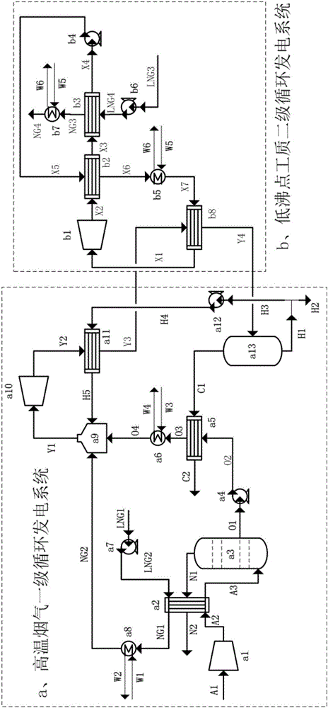
[0033] Such as figure 1 As shown, as a preferred embodiment of the present invention, it includes a high-temperature flue gas primary cycle power generation system and a low boiling point working fluid secondary cycle power generation system.

[0034] In this integrated system, in addition to the external atmospheric pressure, a total of 7 different pressure levels are involved, including compr...


PUM


Abstract

The invention discloses a zero-carbon-emission multistage circulating power generation integrated system which comprises a high-temperature flue gas first-stage circulating power generation system and a low-boiling-point working medium second-stage circulating power generation system. In the high-temperature flue gas first-grade circulating power generation system, LNG cold energy and liquid nitrogen cold energy are applied to the precooling process of the compressed air, and therefore air separation oxygen production power consumption is reduced. The liquid oxygen cold energy is applied to condensation recovery of CO2 in combustion flue gas, and the approximate zero power consumption process of carbon capture is achieved. In the low-boiling-point working medium second-stage circulating power generation system, LNG is adopted as a cold source, environment and combustion flue gas waste heat is adopted as a heat source, the Rankine cycle power generation process of a low-boiling-point working medium is completed, and the output electrical efficiency of the low-boiling-point working medium second-stage circulating power generation system is improved. The zero-carbon-emission multistage circulating power generation integrated system depends on an O2 / H2O high-pressure combustion system of LNG, the low-boiling-point working medium second-stage circulating power generation system is additionally arranged, gradient utilization of energy is achieved, the output electrical efficiency of the integrated system is improved, and meanwhile zero carbon emission of the system is achieved.

Description

technical field [0001] The invention belongs to a zero-carbon emission multi-stage cycle power generation integrated system in the electric power industry, and specifically relates to a high-temperature flue gas primary cycle power generation system and a low boiling point working medium secondary cycle power generation system. Background technique [0002] The greenhouse effect has become the focus of global attention, CO in the atmosphere 2 It is one of the ingredients that contribute the most to the greenhouse effect. Carbon capture and storage technology (Carbon Capture and Storage, CCS) is currently recognized as the most promising CO 2 One of the means of emission reduction. Among them, the oxygen-enriched combustion technology (O 2 / CO 2 ) as one of the easiest technologies to achieve large-scale carbon capture has received extensive attention. Compared with the traditional air combustion system, O 2 / CO 2 The system adds an air separation oxygen production pro...

Claims


Application Information

Patent Timeline
Patent Type & Authority Applications(China)
IPC IPC(8): F01K11/00F25J3/04
CPCF01K11/00F25J3/04266F25J3/044F25J3/04793F25J2200/02F25J2215/50
Inventor 蔡磊吴谋亮管延文刘文斌韩逸骁卢鉴莹余露林奇
Owner HUAZHONG UNIV OF SCI & TECH
Why Eureka
Try Eureka