
Fan for ultrahigh-temperature flue gas treatment

A flue gas treatment and ultra-high temperature technology, which is applied to the components of pumping devices for elastic fluids, mechanical equipment, machines/engines, etc., can solve difficult working temperatures, unguaranteed maintenance cycles, production and maintenance costs. The problem of high cycle time is achieved, and the cooling effect is good, the structure is simple, and the high temperature flue gas leakage and the high temperature spindle cooling effect are solved.

Inactive Publication Date: 2016-12-14
四川三维鼓风机有限公司
View PDF0 Cites 6 Cited by
  • Summary
  • Abstract
  • Description
  • Claims
  • Application Information

AI Technical Summary

Problems solved by technology

[0002] At present, in the field of high-temperature centrifugal fan technology, the working temperature of the fan is usually around 300°C. For example, the working temperature of the high-temperature fan in the denitrification system of a coal-fired power plant is between 300°C and 350°C. However, this high-temperature fan is difficult to apply to higher Operating temperature
In the domestic fan industry, the working temperature is 650°C, the pressure reaches 10kPa and above, and the air volume is 1500Nm 3 The demand for the application of ultra-high-temperature and high-pressure fans with small flow rate and high pressure below 1 / h is increasing; but at present, domestically, such ultra-high-temperature fans have not been applied to the urea pyrolysis system of the flue gas denitrification device of the gas engine thermoelectric F-class unit. There are precedents, and the current domestic gas-fired thermal power F-class units all use imported technology and equipment, and the supporting fans can only be produced by foreign developed countries, resulting in high production and maintenance cost cycles, and often maintenance cycles not guaranteed

Method used


Image

  • Fan for ultrahigh-temperature flue gas treatment
  • Fan for ultrahigh-temperature flue gas treatment

Examples


Embodiment Construction

[0018] The present invention will be further described below in conjunction with the drawings and specific embodiments.

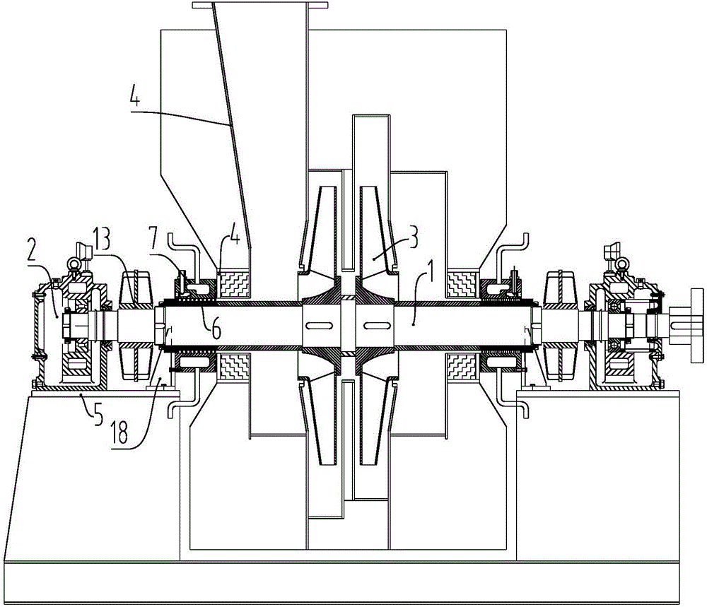
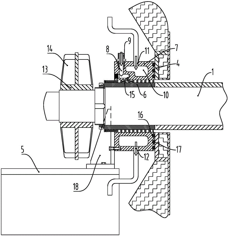
[0019] Such as figure 1 As shown, the fan used for ultra-high temperature flue gas treatment in this embodiment includes a main shaft 1, a bearing box 2 arranged on both ends of the main shaft 1, an impeller 3 and a casing 4 arranged on the main shaft 1, and the bearing boxes 2 are respectively arranged on On the base 5, a set of sealed cooling components are provided on the main shaft 1 on both sides of the casing 4. The sealed cooling components include a sealing component and a cooling component arranged on the fan main shaft 1, and the sealing component includes a sealing sleeve and The sealing sleeve 6, the sealing sleeve 6 is arranged on the main shaft 1, and the sealing sleeve and the sealing sleeve 6 cooperate to form a labyrinth seal. The compressed air passage 8 is provided in the sealing sleeve, and the compressed air passage 8 communicates with the ...


PUM


Abstract

The invention relates to the technical field of fans and particularly relates to a fan for ultrahigh-temperature flue gas treatment, which is capable of working at the temperature of 650 DEG C and resistant to the highest temperature of 800 DEG C. The fan comprises a main shaft, bearing boxes arranged at two ends of the main shaft, an impeller arranged on the main shaft and a machine shell; each bearing box is arranged on a base; the main shaft is provided with sealing and cooling assemblies respectively located at two sides of the machine shell; and each sealing and cooling assembly comprises a sealing assembly and a cooling assembly which are arranged on the main shaft of the fan. Two sides of the machine shell of the fan are provided with the sealing and cooling assemblies for sealing and cooling the machine shell and the main shaft, and the sealing assembly and the cooling assembly are of an integral structure, so that the fan is simpler in structure; due to the adoption of the sealing and cooling assemblies, the sealing and cooling effects of the fan are good, and the problems of high-temperature flue gas leakage and high-temperature main shaft cooling can be effectively solved; and the temperature on the position of a bearing on the main shaft can be reduced to be lower than 60 DEG C, so that the normal operation of the fan at high temperature can be ensured.

Description

Technical field [0001] The invention relates to the technical field of fans, in particular to a fan with a working temperature of 650°C and a maximum temperature resistance of 800°C, which is used for ultra-high temperature flue gas treatment. Background technique [0002] At present, in the technical field of high-temperature centrifugal fans, the working temperature of fans is usually around 300°C. For example, the working temperature of high-temperature fans in the denitration system of coal-fired power plants is between 300°C and 350°C, but such high-temperature fans are difficult to apply to higher temperatures. Operating temperature. In the domestic fan industry, the working temperature is 650℃, the pressure is 10kPa and above, and the air volume is 1500Nm 3 The application demand for small flow, high pressure, ultra-high temperature and high pressure fans with a flow rate of 1 / h and below is increasing; however, domestic ultra-high temperature fans have not been applied t...

Claims


Application Information

Patent Timeline
Patent Type & Authority Applications(China)
IPC IPC(8): F04D29/10F04D29/58
CPCF04D29/102F04D29/584
Inventor 黄维伦易立王煜威
Owner 四川三维鼓风机有限公司
Learn More