
Control system of sewage treatment plant

A sewage treatment plant and control system technology, applied in the environmental field, can solve problems such as many variables, difficulty in obtaining control effects, unstable effluent quality, etc., and achieve the effect of a high level of automation

Inactive Publication Date: 2016-12-14
马占久
View PDF4 Cites 18 Cited by
  • Summary
  • Abstract
  • Description
  • Claims
  • Application Information

AI Technical Summary

Problems solved by technology

Most of the detection instruments used in some sewage treatment are off-line instruments with poor accuracy and reliability. The monitoring method is also to measure after sampling, and then adjust the operating status of the equipment according to the measurement results.
Therefore, it is difficult to carry out fast and effective online real-time control, which often leads to unstable water quality
The sewage biochemical treatment process is a typical nonlinear, time-varying, uncertain, and large-delay complex large-scale system. Its modeling and control pose severe challenges to the control community.
This paper summarizes the status quo of sewage treatment process control as follows: 1) Due to the simple control, traditional control methods (conventional control, optimal control, adaptive control) are still widely used, but because of the large number of variables in the sewage treatment process, the process is nonlinear, Strong coupling and other characteristics, and various parameters are also time-varying, so traditional control methods based on precise mathematical models are difficult to achieve ideal control effects; 2) Although intelligent control has become the frontier and hot spot in the research and application of sewage treatment, but It is still in the initial stage of wide application at home and abroad

Method used

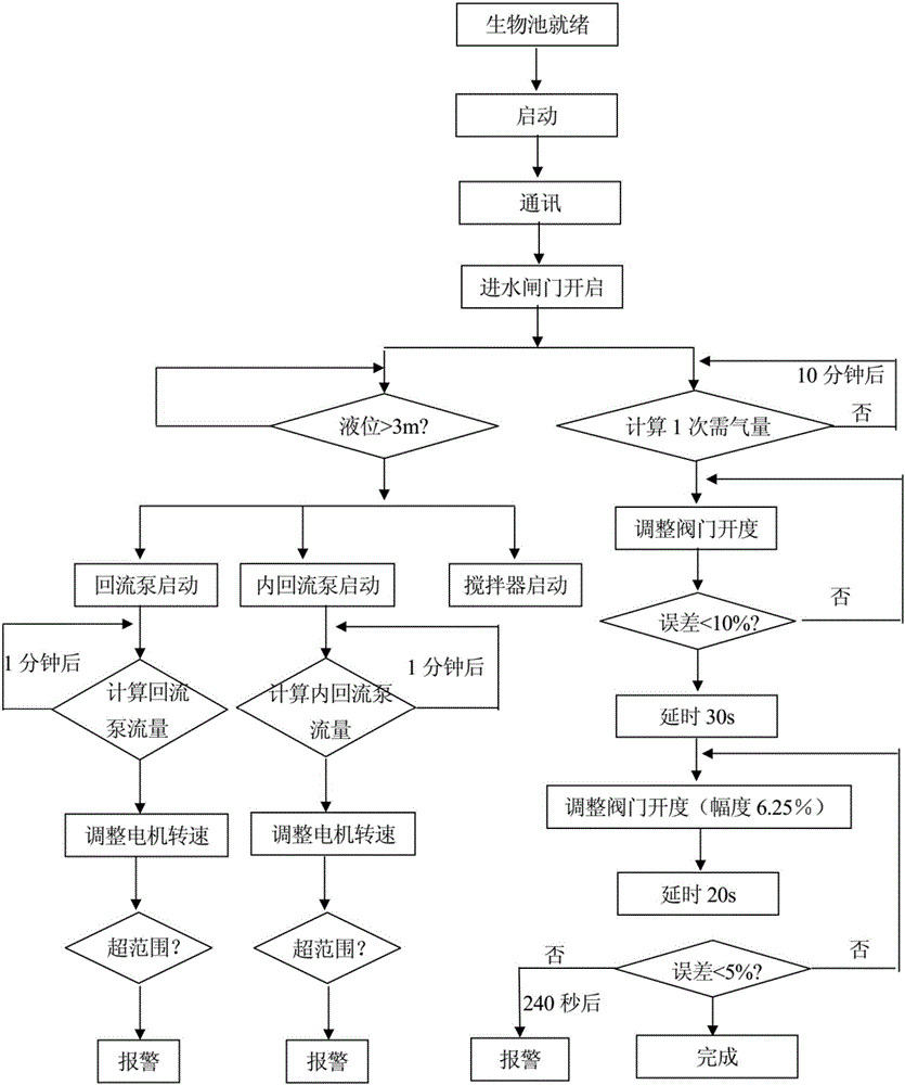
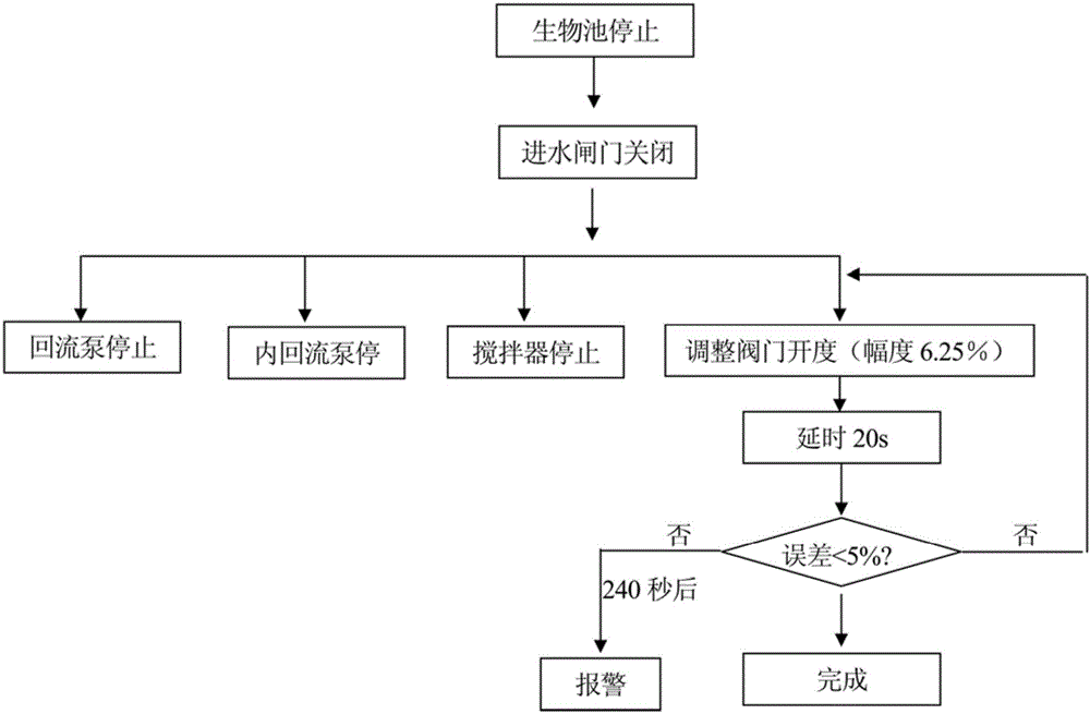

Image

  • Control system of sewage treatment plant
  • Control system of sewage treatment plant
  • Control system of sewage treatment plant

Examples


Embodiment Construction

[0010] In order to make the above-mentioned purposes, features and advantages of the present invention more obvious and understandable, the specific implementation modes of the present invention will be described in detail below in conjunction with the accompanying drawings, so that the above-mentioned and other purposes, features and advantages of the present invention will be clearer. Like reference numerals designate like parts throughout the drawings. The drawings have not been drawn to scale, emphasis instead being placed upon illustrating the gist of the invention.

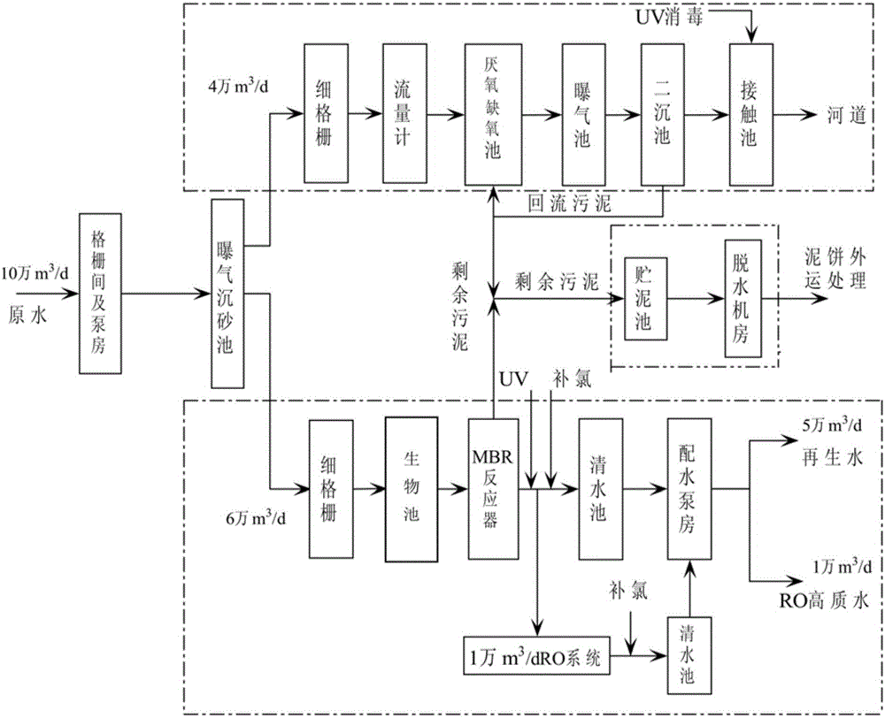
[0011] First, the sewage treatment process of the present invention is introduced, please refer to figure 1 , the sewage in the watershed of the sewage treatment plant is connected to the water collection well of the lifting pump room through the water inlet pipeline, and passes through two grid rooms equipped with 8mm thick grids, where large impurities in the sewage are intercepted and then enters the sewa...


PUM


Abstract

The invention discloses a control system of a sewage treatment plant. Sewage in the watershed of the sewage treatment plant enters a water collecting well of a lifting pump station through a water inlet pipeline, after large impurities in the sewage are intercepted through two grating chambers containing 8-mm coarse gratings, the sewage enters a sewage lifting pump station, the sewage is lifted and then flows into an aerated grit chamber to remove sand, and then sewage is divided into two systems; in one system, after passing through 1-mm fine gratings, the sewage flowing at the speed of 60,000 m<3> / d passes through a biological tank and then enters an MBR membrane biological reaction tank to remove contaminants such as COD, BOD5, N and P. The control system is good in sewage treatment effect.

Description

technical field [0001] The invention belongs to the field of environment, in particular to a sewage treatment plant control system. Background technique [0002] In recent years, the Chinese government has begun to pay attention to environmental pollution. Especially after the sustainable development strategy was proposed, the government has also paid attention to environmental protection and governance while the economy is developing rapidly. Environmental protection has become one of the basic national policies of our country. From the perspective of environmental governance in recent years, there is not much difference between my country's environmental protection theory, process research and application and foreign countries. The gap is relatively large in environmental protection unit equipment and automatic control systems. The status quo of the automatic control system of my country's sewage treatment plants is: both manual and automatic, self-made and imported simul...

Claims


Application Information

Patent Timeline
Patent Type & Authority Applications(China)
IPC IPC(8): G05B19/05C02F9/14
CPCG05B19/05C02F9/00
Inventor 马占久
Owner 马占久
Learn More