
Wound-rotor brushless doubly-fed motor control device and control method

A technology of a control device and a control method, applied in the direction of a current controller, etc., can solve the problems of limited operating frequency range, operating failure, pulsation and large noise of a brushless doubly-fed motor, and achieve easy implementation of the control method and high dynamic response. Safe and reliable control and operation

Inactive Publication Date: 2016-12-14
北京国电四维清洁能源技术有限公司
View PDF5 Cites 0 Cited by
  • Summary
  • Abstract
  • Description
  • Claims
  • Application Information

AI Technical Summary

Problems solved by technology

This kind of method will still bring the impact of several times the rated current when cutting into the power winding power supply, and the motor speed will change drastically, which is extremely unfavorable to the load operation
[0004] At present, the brushless doubly-fed motor starting device in the prior art cannot reduce the damage caused by the inrush current to the motor, and the operation process is complicated, and it is prone to operation failure, resulting in operation failure; and it needs to add supporting components such as short-circuit resistors, which increases the cost ; And the volume is generally large, occupying too much space on site, which brings inconvenience to installation, construction and maintenance
[0005] Moreover, the existing technical solutions cannot realize full-frequency band control when the brushless doubly-fed motor is running, and in some operating frequency bands, out-of-step faults will occur, resulting in a limited operating frequency range of the brushless doubly-fed motor; and the prior art The scheme controls the pulsation and noise of the brushless double-fed motor during operation, which reduces the life of the brushless double-fed motor and affects the stability of the load operation; occasions with high time requirements

Method used


Image

  • Wound-rotor brushless doubly-fed motor control device and control method
  • Wound-rotor brushless doubly-fed motor control device and control method
  • Wound-rotor brushless doubly-fed motor control device and control method

Examples


Embodiment Construction

[0047] The specific embodiments of the present invention will be further described below in conjunction with the accompanying drawings. It should be noted here that the descriptions of these embodiments are used to help understand the present invention, but are not intended to limit the present invention. In addition, the technical features involved in the various embodiments of the present invention described below may be combined with each other as long as they do not constitute a conflict with each other.

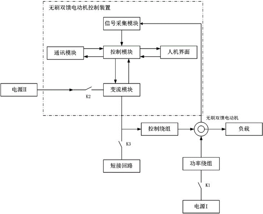
[0048] figure 1It is a structural schematic diagram of a wound rotor brushless doubly-fed motor control device in an embodiment, including a contactor K1 for switching on and off the power supply of the power winding, and the power supply I on the power winding side can be 380V, 690V, 1140V, 6kV, One of the 10kV three-phase power frequency AC power supplies; it also includes contactor K2, which is used to control the power supply of the control device. The power supply ...


PUM


Abstract

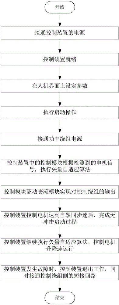
The invention discloses a wound-rotor brushless doubly-fed motor control device and control method. The wound rotor brushless doubly-fed motor control method comprises: a power supply of a control device is switched on and a control device is ready; after the control device is ready, parameters are set on a human-machine interface; a startup operation is executed; a power winding power supply is switched on; a control module in a control device executes a vector adaptive control algorithm according to a detected motor signal; the control module drives a converter module to realize output on a control winding; after the control device controls the motor to achieve natural synchronous speed, a non-impact starting process is finished; after the starting is finished, the control device controls the motor to operate with accelerated speed or reduced speed according to a set frequency and a set torque parameter; and when the control device is failed, the control device quits working and a short circuit loop on a control winding side is switched on.

Description

technical field [0001] The invention relates to the technical field of brushless doubly-fed motors, in particular to a control device and control method for a winding rotor brushless doubly-fed motor. Background technique [0002] Brushless doubly-fed motor is a new type of AC speed-regulating motor in recent years. It consists of two sets of independent stator windings (power winding and control winding) and rotor. It uses a reversible frequency converter to adjust the power supply frequency of the control winding to realize the control of the motor. speed control. The traditional high-power brushless doubly-fed motor starting device adopts the method of controlling the series resistance of the winding or the series resistance of the drive circuit inside the frequency converter, and the low-power brushless doubly-fed motor adopts the method of directly shorting the control winding. In these traditional methods, the peak current of the motor is very large, and the high curr...

Claims


Application Information

Patent Timeline
IPC IPC(8): H02P6/28
Inventor 樊军李明才吴限富王勇
Owner 北京国电四维清洁能源技术有限公司
Learn More