

Novel busbar and manufacturing method thereof
A busbar, a new type of technology, applied in the direction of chemical instruments and methods, printed circuit manufacturing, cable/conductor manufacturing, etc., can solve the problems that do not conform to the development trend of product miniaturization, cannot realize circuit connection, and is easy to generate electromagnetic interference, etc., to achieve Good product quality, reduce electromagnetic interference, and maintain the effect of product quality
- Summary
- Abstract
- Description
- Claims
- Application Information
AI Technical Summary
Problems solved by technology
Method used
Image

Examples
Embodiment 1
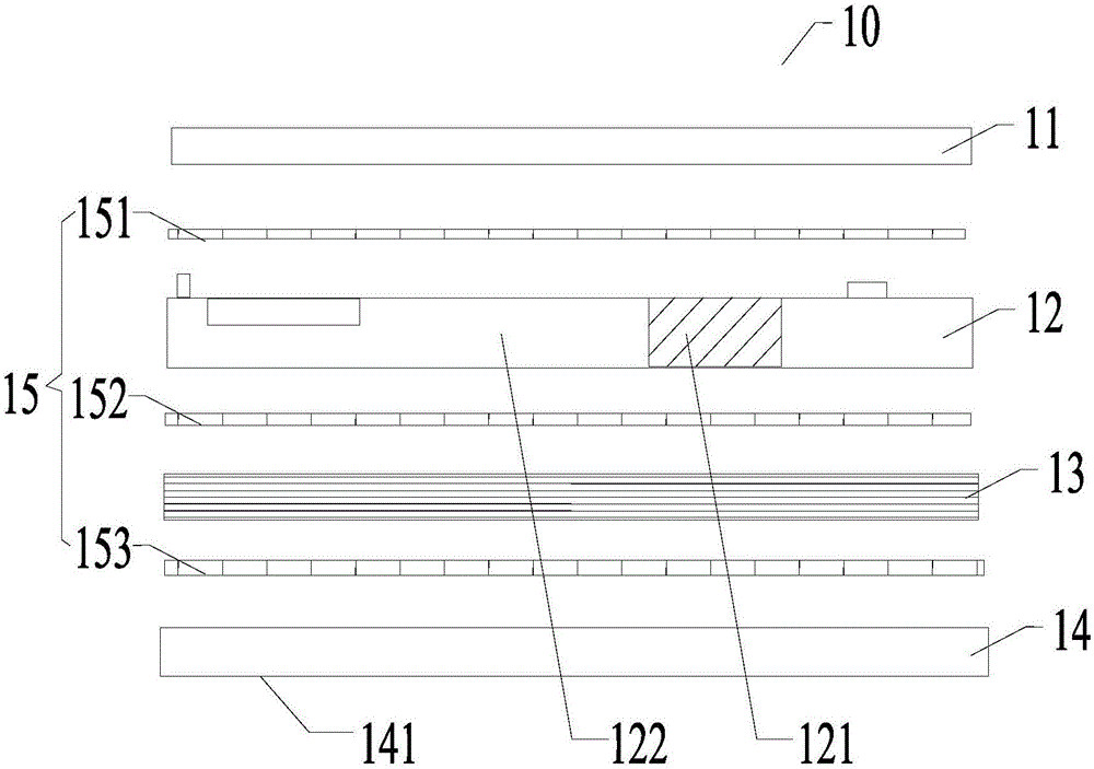
[0041] Please refer to figure 1 , the embodiment of the present invention provides a new busbar 10 .
[0042] The novel busbar 10 includes the following layers pressed together in sequence: an insulating layer 11, a busbar 12, an insulating material 13, and a printed circuit board PCB 14;
[0043] Wherein, there is an adhesive sheet 15 between any adjacent two layers of the insulating layer 11, the busbar 12, the insulating material 13, and the PCB 14;
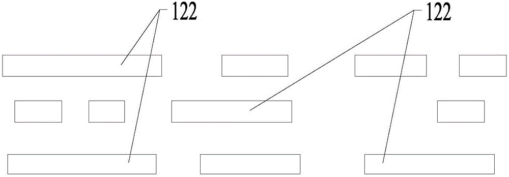
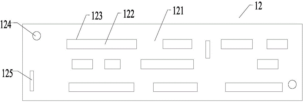
[0044] The busbar 12 is inlaid by insulating plates 121 and copper bars 122;
[0045] The busbar 12 is electrically connected to the PCB 14 through an interlayer conductive structure.
[0046] Wherein, the bonding sheet 15 may include: a first bonding sheet 151 between the insulating layer 11 and the busbar 12, a second bonding sheet 152 between the busbar 12 and the insulating material 13, and a second bonding sheet 152 between the insulating layer 11 and the insulating material 13. A third adhesive sheet 153 between the m...
Embodiment 2
[0075] Please refer to Figure 4 , an embodiment of the present invention provides a method for manufacturing a new type of busbar, which may include:
[0076] 400. Material selection and blanking:
[0077] In the embodiment of the present invention, by analyzing the laminated structure and high temperature resistance characteristics of the new busbar, and after a series of experimental verifications, several insulating materials and glue systems that meet this scheme are obtained.
[0078] Such as figure 1 As shown, the novel busbar 10 includes the following layers: an insulating layer 11, a busbar 12, an insulating material 13, and a printed circuit board PCB 14; The insulating board 121 and the copper bar 122 are inlaid.
[0079] Optionally, the insulating plate 121 and the insulating material 13 are made of FR4 material;
[0080] Optionally, the insulating layer 11 is made of NOMEX (NOMEX) material;
[0081] Optionally, the bonding sheet 15 adopts a halogen-free flame...
PUM
 Abstract
Description
Claims
Application Information