Pressure relief device for ultra-high pressure sterilization apparatus
A technology of ultra-high pressure sterilization and pressure relief device, applied in application, food science, food preservation, etc., can solve the problems of slow drainage, inability to alleviate the safety of ultra-high pressure containers, and inability to quickly release pressure in high-pressure pipelines, to prevent Deformation, shortening the pressurization time and pressure relief time, and the effect of ensuring safety
- Summary
- Abstract
- Description
- Claims
- Application Information
AI Technical Summary
Problems solved by technology
Method used
Image
Examples
Embodiment approach
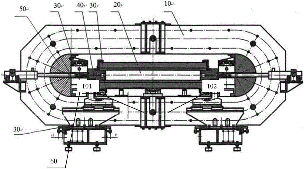
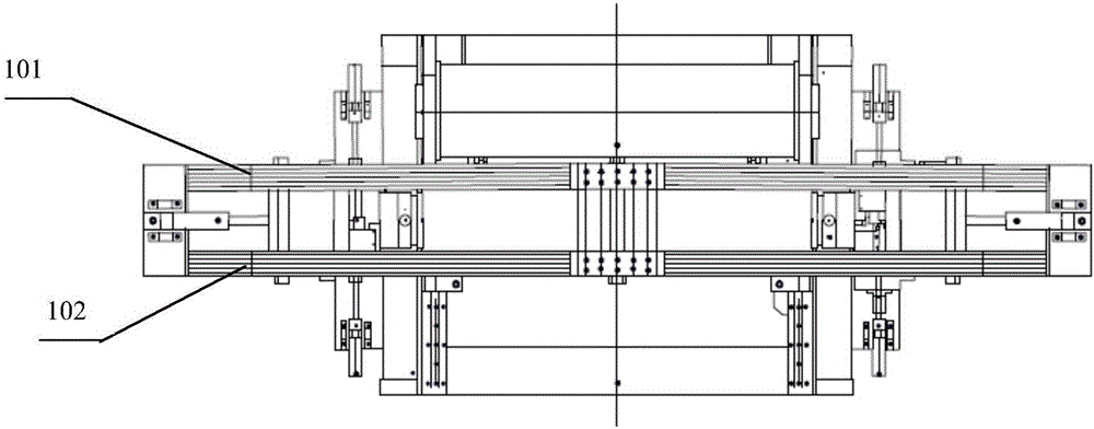
[0060] According to a preferred embodiment, the outer side of the load-bearing frame of the present invention is a load-bearing frame with a broken line structure with an inner angle of 120° to 140°. The zigzag structure is formed by cutting off four corners of each layer of rectangular plates along a consistent tangent line, and the extension lines of the tangent lines intersect each other to form a parallelogram. Preferably, the extension lines intersect to form a square. The mutual contact area between each layer of steel plates is greater than 80% of their relative areas, and the ratio of the width of the gap between two groups of plates to the thickness of each group of plates is 1-3:1, preferably 2.5:1. In addition, the ratio of the width of the inner frame of the load-bearing frame to the thickness of the frame is 2 to 1:1, preferably 1.5:1; in addition, the aspect ratio of the inner frame is 5 to 6:1, preferably 6 :1, the aspect ratio of the outer frame is 2-4:1, prefe...
Embodiment 1
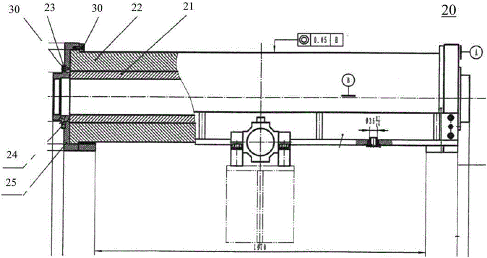
[0084] The preparation process of the load-bearing frame at least includes: the pre-assembly of the alloy steel plates of the load-bearing frame, the alignment and adjustment of the opening arcs of the alloy steel plates of the load-bearing frame, and the welding of the alloy steel plates of the load-bearing frame. The assembly process of the first load-bearing frame or the second load-bearing frame specifically includes: using 38 pieces of M27*200mm outer hexagon bolts to pre-assemble 6 pieces of stacked plates on the flat plate, and at the same time, it is necessary to ensure that each piece of load-bearing frame cannot have For flash, burrs, bumps, and oil stains, the placement of the workpiece should be consistent with the placement of the water cutting process. The upper and lower parts should choose R435 water cutting with the best quality; place the two semicircular blocks in the arcs on both sides of the 6 load-bearing frames. , and connect the two semi-circular blocks ...
Embodiment 2
[0090] In this embodiment, on the basis of Embodiment 1, the pressure relief device is further described.
[0091] The pressure relief device for an ultrahigh pressure sterilization device of the present invention includes an ultrahigh pressure chamber, at least one ultrahigh pressure source, a booster linear valve, at least one pressure sensor, at least one proportional pressure relief valve and a control module. The control module adjusts the boosting slope of each pressure stage based on the ultra-high pressure indication in the ultra-high pressure cabin monitored by the pressure sensor and the boost linear valve connected to the ultra-high pressure source, so that the ultra-high pressure approaches a sinusoidal waveform The changing curve of the rising curve is rapidly boosted. After the ultra-high pressure in the ultra-high pressure cabin is stabilized, the control module adjusts at least one proportional pressure relief valve connected to the ultra-high pressure pipeline...
PUM
 Abstract
Description
Claims
Application Information
 - R&D
- Intellectual Property
- Life Sciences
- Materials
- Tech Scout
- Unparalleled Data Quality
- Higher Quality Content
- 60% Fewer Hallucinations
Browse by: Latest US Patents, China's latest patents, Technical Efficacy Thesaurus, Application Domain, Technology Topic, Popular Technical Reports.
© 2025 PatSnap. All rights reserved.Legal|Privacy policy|Modern Slavery Act Transparency Statement|Sitemap|About US| Contact US: help@patsnap.com


