Construction waste treatment system
A technology for processing system and construction waste, applied in the direction of grain processing, etc., can solve the problems of ineffective utilization of resources, secondary pollution of ground soil, limited economic benefits, etc.
- Summary
- Abstract
- Description
- Claims
- Application Information
AI Technical Summary
Problems solved by technology
Method used
Image
Examples
Embodiment 1
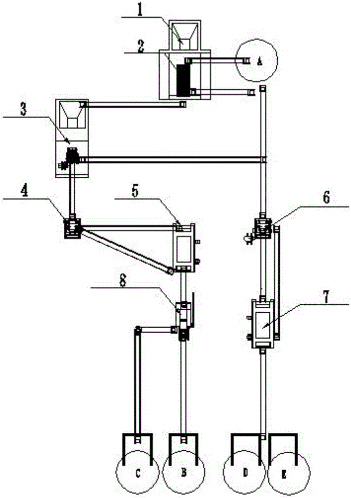
[0041] Such as figure 1As shown, the construction waste treatment system provided in this embodiment includes a feeder 1, a brick-mix separator 2, a first jaw crusher 3, a first impact crusher 4, a second impact crusher 6, The first vibrating screen 5, the second vibrating screen 7 and the light matter removal device 8; the feeder 1, the brick-mixing separator 2, the first jaw crusher 3, the first impact crusher 4, the first vibrating The screen 5 and the light matter removal device 8 are connected in sequence; the brick-concrete separator 2, the second impact crusher 6 and the second vibrating screen 7 are connected in sequence, and the second impact crusher 6 is arranged on the brick Below the mixing separator 2.
[0042] The construction waste treatment system provided in this embodiment uses the brick-mix separator 2 to separate the bricks and concrete in the construction waste materials to obtain the separated bricks and concrete. On the one hand, the first jaw crusher 3...
Embodiment 2
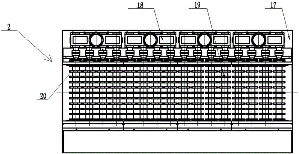
[0046] The structures of the feeder, the first jaw crusher, the first impact crusher, the second impact crusher, the first vibrating screen and the second vibrating screen in the construction waste treatment system provided in Embodiment 1 can all be adopted The structure commonly used in the prior art will not be repeated here, and the preferred structure of the brick-concrete separator 2 will be described below emphatically.
[0047] Such as figure 2 , 3 As shown, the preferred structure of the brick-concrete separator 2 provided in this embodiment is as follows: the brick-concrete separator 2 includes a frame 17, a driving device 18 and a roller 19 arranged on the frame 17; There are a plurality of shafts 19, a plurality of rollers 19 are arranged at intervals, and the driving device 18 is connected with the rollers 19 for driving the rotation of the rollers 19; the outer wall of the rollers 19 is along the A plurality of annular blades 20 are arranged at intervals in th...
Embodiment 3
[0054] The structures of the feeder, the first jaw crusher, the first impact crusher, the second impact crusher, the first vibrating screen and the second vibrating screen in the construction waste treatment system provided in Embodiment 1 can all be adopted The structures commonly used in the prior art will not be repeated here, and the preferred structure of the light matter removal device will be described below emphatically.
[0055] Such as Figure 4 As shown, the light matter removal device includes a chain conveyor belt 10 and a plurality of scrapers 11; a plurality of the scrapers 11 are arranged at intervals on the chain conveyor belt 10 for scraping light substances floating on the water surface. matter, the scraping shaker 11 is provided with a containing cavity, and the bottom of the containing cavity has a mesh structure for storing scraped light matter.
[0056] In one implementation of this embodiment, the scraper 11 can be made of metal materials, such as stee...
PUM
 Abstract
Description
Claims
Application Information
 - R&D
- Intellectual Property
- Life Sciences
- Materials
- Tech Scout
- Unparalleled Data Quality
- Higher Quality Content
- 60% Fewer Hallucinations
Browse by: Latest US Patents, China's latest patents, Technical Efficacy Thesaurus, Application Domain, Technology Topic, Popular Technical Reports.
© 2025 PatSnap. All rights reserved.Legal|Privacy policy|Modern Slavery Act Transparency Statement|Sitemap|About US| Contact US: help@patsnap.com


