A solid thermal agent cutting bomb

A kind of cutting bullet and solid technology, which is applied in the direction of welding/cutting medium/material, welding equipment, manufacturing tools, etc., can solve the problems of shortened cutting time, loud firing noise of primer, fast burning speed of cutting agent, etc., and achieves low cutting cost, The effect of low noise and reducing ablation pollution

Active Publication Date: 2019-02-12
PEOPLES LIBERATION ARMY ORDNANCE ENG COLLEGE
View PDF5 Cites 2 Cited by
  • Summary
  • Abstract
  • Description
  • Claims
  • Application Information

AI Technical Summary

Problems solved by technology

However, during use, it was also found that since the cutting bullet needs to be opened and loaded from the rear end of the cutting gun chamber, and then the gun chamber is closed, the ignition method is to ignite the cutting agent by firing the primer at the rear end of the cutting bullet. The structure of the cutting gun is complicated, and the primer fires noise. Large, interferes with manual operation, and the burned cutting bullets are ejected from the rear end of the barrel, which is easy to ablate and pollute the inner wall of the gun barrel, reducing the service life of the cutting gun; the structure of the cutting bullet is still complicated, difficult to manufacture, and high in cost. The hollow structure of fine particle components, bumps and vibrations in the process of storage, transportation and use can easily cause the cutting agent to break and scatter, affecting the cutting agent's combustion mode, causing the cutting agent to burn too fast, shorten the cutting time, and deteriorate the operability And other problems, affect the cutting quality

Method used


Image

  • A solid thermal agent cutting bomb

Examples


Embodiment Construction

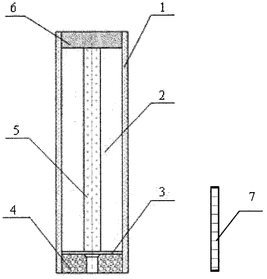
[0015] The outer diameter is 26.5mm solid thermal agent cutting ammunition, the full length of the ammunition is 93mm, and the cartridge case is a 1.5mm thick paper tube. First, press-fit the 8mm thick mud plug on the bottom of the cartridge case, and then bond it to the inner diameter of the cartridge case with water glass adhesive.

[0016] Cutting agent composition weight percentage is Fe 3 o 4 (-200 mesh) 20%, Fe 2 o 3 (-200 mesh) 38%, CuO (-200 mesh) 2%, Al (-250 mesh) 20%, KNO 3 (-100 mesh) 10%, CaCO 3 (-100 mesh) 1%, Al 2 o 3 (-150 mesh) 1%, SiO 2 (-200 mesh) 0.6%, Ni (-150 mesh) 6%, Zr (-100 mesh) 1%, and trace components; the above materials were ball milled and sieved, and dried at 120°C for 2 hours, and the cutting agent solid powder was prepared according to the formula Mix evenly, put into a self-made molding machine, and press into a hollow structure grain column, and the hollow hole diameter is about 6mm.

[0017] The weight percentage of quick-burning a...


PUM

PropertyMeasurementUnit
diameteraaaaaaaaaa
lengthaaaaaaaaaa
diameteraaaaaaaaaa

Abstract

The invention discloses a solid thermit jet cutter. The solid thermit jet cutter includes a shell case, a plug, a rapid combustion agent, a cutting agent, a separating sheet, a nozzle and a fuse; the shell case is a paper tube; the plug is made of a high-temperature resistance plastic material or a ceramic material; the high energy cutting agent is a hollow structure compressed by mixed solid powder; a channel is filled with the rapid combustion agent, and a solid dual-grain structure is formed; the straight-flow type nozzle made of a graphite material is arranged on the internal front end of the cutter; the separating sheet is arranged between the nozzle and the cutting agent and the rapid combustion agent; and the fuse is a special hard columnar inflammable material. During cutting, the jet cutter is arranged in a special cutting torch, the fuse is introduced from the nozzle, the rapid combustion agent is ignited after the fuse is ignited, the rapid combustion agent ignites the inner wall of the grain instantly, a high-temperature product is gathered and compressed via the nozzle and then is ejected to fuse and combust a cutting piece locally, and then the high-temperature product is blown down by high-pressure gas, and manual thermit cutting can be achieved. The jet cutter is simple in structure, is easy and reliable to operate, is high in cutting efficiency, is wide in application, and can be used for rapid emergent thermal cutting without electricity, gas, and devices.

Description

technical field [0001] The invention relates to the field of emergency cutting, in particular to a solid thermal agent cutting bomb suitable for manual thermal cutting in the field without power supply, gas source and equipment. Background technique [0002] In the emergency installation, repair and demolition of field engineering facilities and equipment, in the emergency rescue and daily fire rescue of earthquakes, snowstorms, landslides, shipwrecks and other disasters, there is an urgent need for a portable safety device without power supply, gas source and equipment. quick emergency cutting method. Rapid emergency cutting is also a necessary means for the army to repair the battlefield. In the field conditions, damaged equipment parts are stuck, broken, perforated and other damages, which seriously affect the performance of the equipment. Emergency cutting and rapid repair are required. Through emergency rapid repair or disassembly, Quickly restore the combat effectiven...

Claims


Application Information

Patent Timeline
Patent Type & Authority Patents(China)
IPC IPC(8): B23K28/00B23K35/34
CPCB23K28/00B23K35/34
Inventor 辛文彤崔秀梅孙立明孙宏涛李志尊李宝峰刘榆华
Owner PEOPLES LIBERATION ARMY ORDNANCE ENG COLLEGE
Why Eureka
Try Eureka