
Internal temperature control liquid piston device for isothermal compressed air energy storage

A compressed air energy storage, high-pressure gas technology, applied in engine components, machines/engines, mechanical equipment, etc., can solve problems such as large energy loss, solve damage and harm, help temperature control, and improve energy utilization efficiency. Effect

Active Publication Date: 2016-12-21
NORTH CHINA ELECTRIC POWER UNIV (BAODING)
View PDF5 Cites 9 Cited by
  • Summary
  • Abstract
  • Description
  • Claims
  • Application Information

AI Technical Summary

Problems solved by technology

[0006] Aiming at the problems of heat loss in the compression process of traditional compressed air energy storage and large energy loss due to pressure drop caused by low temperature during expansion, the present invention proposes an internal temperature-controlled liquid piston device for isothermal compressed air energy storage, including: pressure The container is connected with the low-pressure gas pipeline and the high-pressure gas pipeline, and the bottom of the pressure vessel is connected with the hydraulic potential energy conversion device. The pressure vessel cavity is provided with packing or trays or a combination of packing and trays to promote gas-liquid heat exchange, and a liquid is placed above the pressure vessel. Distributor, the two ends of the temperature control liquid injection device are respectively connected with the upper and lower parts of the pressure vessel

Method used


Image

  • Internal temperature control liquid piston device for isothermal compressed air energy storage
  • Internal temperature control liquid piston device for isothermal compressed air energy storage
  • Internal temperature control liquid piston device for isothermal compressed air energy storage

Examples


Embodiment Construction

[0044] The embodiments will be described in detail below in conjunction with the accompanying drawings.

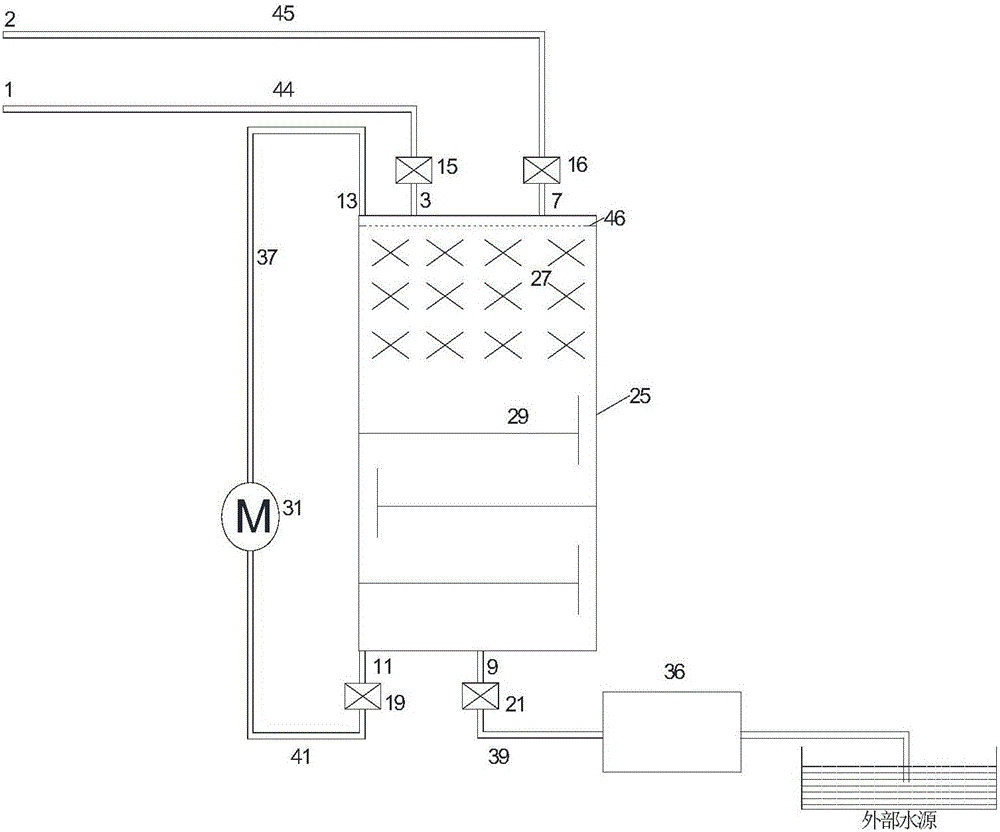
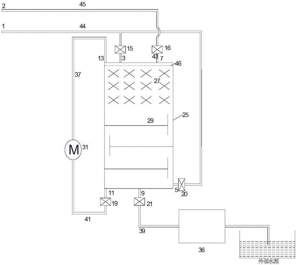
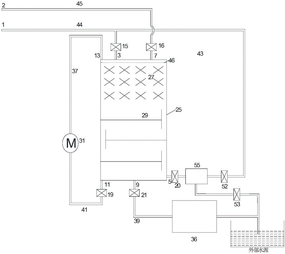
[0045] figure 1 and figure 2 It is two connection methods of high-pressure pipelines for internal temperature-controlled liquid piston devices used for isothermal compressed air energy storage. The pressure vessel 25 is connected to the high-pressure gas pipeline 1, the low-pressure gas pipeline 2, and the hydraulic potential energy conversion device 36, and the two ends of the temperature control liquid injection device 31 are respectively connected to the top and bottom of the pressure vessel, and the hydraulic potential energy conversion device 36 is connected to an external water source; the pressure vessel A liquid distributor 46, a filler 27, and a tray 29 are provided from top to bottom.

[0046] figure 1 The connection mode of the high-pressure gas pipeline shown is: the high-pressure gas pipeline is only connected to the top of the pressure vessel, and serves ...


PUM


Abstract

The invention belongs to the technical field of liquid pistons and the technical field of compressed air energy storage, and in particular, relates to an internal temperature control liquid piston device for isothermal compressed air energy storage. The device comprises a pressure container (25) connected with a low-pressure gas pipe (2) and a high-pressure gas pipe (1); a hydraulic potential conversion device (36) is connected to the bottom of the pressure container; a filler (27) or a tower plate (29) for accelerating gas-liquid heat exchange is arranged in a cavity of the pressure container; a liquid distributor (46) is arranged on the upper side in the cavity of the pressure container; and two ends of a temperature control liquid injecting device (31) are respectively connected with the upper part and the lower part of the pressure container. The device has two working modes of gas energy storage and energy release; the temperature control liquid injecting device and the liquid distributor enable temperature control liquid to uniformly flow down from the upper part of the pressure container; the gas and the liquid make direct contact for quick heat exchange; and the filler and a flat plate are provided for increasing the gas-liquid heat exchange contact area and prolonging the contact time to improve the gas-liquid heat exchange efficiency in the container. The device controls the gas temperature by using the characteristic of high specific heat of the liquid to realize similar gas isothermal zooming effect.

Description

technical field [0001] The invention belongs to the technical fields of liquid piston and compressed air energy storage, and in particular relates to an internal temperature-controlled liquid piston device for isothermal compressed air energy storage. Background technique [0002] With the development of the power system, energy storage technology plays an increasingly important role in the stability and economy of the power grid. At the same time, energy storage technology assists new energy power generation, which can effectively solve the problems of new energy volatility, intermittency, randomness, etc., so that it can form a continuous and stable energy output. However, the existing large-capacity energy storage technologies only have pumped hydro storage and compressed air energy storage. Pumped hydro storage has disadvantages such as harsh requirements on the geographical environment and long construction period; while compressed air energy storage has no such limita...

Claims


Application Information

Patent Timeline
IPC IPC(8): F01B29/00F01B31/00
CPCF01B29/00F01B31/00
Inventor 姜彤郑祥常陈紫薇傅昊
Owner NORTH CHINA ELECTRIC POWER UNIV (BAODING)
Learn More