Solar thermal energy power system based on pressurization condensation

A technology of solar thermal energy and power system, which is applied in the direction of using solar energy to generate mechanical power, solar thermal power generation, and mechanisms for generating mechanical power. problems, to achieve the effect of improving gasification efficiency and condensation efficiency, stabilizing gasification temperature and working medium flow rate, and avoiding unstable turbine speed

Inactive Publication Date: 2016-12-21
郭远军
View PDF0 Cites 0 Cited by
  • Summary
  • Abstract
  • Description
  • Claims
  • Application Information

AI Technical Summary

Problems solved by technology

[0007] However, the common problems of existing thermal power generation equipment are: a. The temperature requirements for high-temperature heat sources are high, generally above 200°C, and the thermal energy conversion efficiency is low, and the thermal energy conversion efficiency is generally 15% to 35%; b. The heat displacement of the condensing device is large, and the waste of heat energy is large. The condensation speed through the natural condensation method is slow, and the active condensation method (fan air cooling or liquid pump water cooling) requires additional power consumption; c. The turbine is prone to leakage of working fluid Problems; d. Turbine speed is unstable, and it is prone to stuck problems; e. The heat collection effect of the heat collector is not good, and the external waste heat absorption rate is small; f. The gasification temperature of the working medium is unstable, and the condensation effect of the working medium is not good , the working medium is easy to deteriorate or appear impurities; g. The existing equipment is relatively large
[0008] In the process of realizing the power output of existing solar energy, the photoelectric effect is first required to convert it into electrical energy, and then output power through electric equipment; at this stage, the equipment used to convert solar energy into electrical energy is mainly a photovoltaic panel. At about 5%, energy waste is serious

Method used


Image

  • Solar thermal energy power system based on pressurization condensation
  • Solar thermal energy power system based on pressurization condensation
  • Solar thermal energy power system based on pressurization condensation

Examples


Embodiment 1

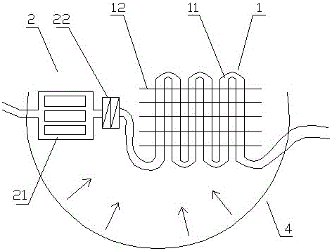
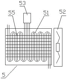
[0076] Embodiment one (such as figure 1 shown): a solar thermal power system based on pressurized condensation, including a heat collector 1, a gasification device 2, a turbine 3, a solar concentrating cover 4, a condensation device 5, a circulation pipeline 6, a circulation medium 7 and a unit The hydraulic pump 9, the heat collecting device 1, the gasification device 2, the turbine 3, the condensing device 5 and the one-way hydraulic pump 9 realize circulation communication through the circulation pipeline 6 in sequence, and the circulation pipeline 6 contains a circulating working medium 7;

[0077] (Such as figure 2 As shown), the heat collecting device 1 and the gasification device 2 are installed in the solar concentrating cover 4, and the heat collecting device 1 includes solar heat collecting tubes 11 and solar heat collecting fins 12, and the solar heat collecting fins 12 are distributed in parallel at intervals, and the solar energy The heat collecting tube 11 is f...

Embodiment 2

[0090] Embodiment two (such as Figure 6 shown): The difference from Embodiment 1 is that the solar heat collecting sheet 12 of the heat collecting device 1 is in the shape of a curved sheet.

[0091] Through experiments on the solar thermal energy power system based on pressurized condensation in the above-mentioned embodiment 2, the gasification temperature of the working fluid reaches 50°C, 55°C, 60°C, 65°C, and 70°C respectively under different intensities of sunlight irradiation When the temperature of the cold source is 18°C, the flow rate of the working medium in the circulation pipe is adjusted according to the operation stability of the solar thermal energy power system based on pressurized condensation; the experimental results are: when the gasification temperature of the working medium is about 50°C, the heat energy The conversion efficiency is about 17.5%. When the gasification temperature of the working fluid is about 55°C, the thermal energy conversion efficien...

Embodiment 3

[0092] Embodiment three (such as Figure 7 shown): The difference from Embodiment 1 is that the solar heat collecting fins 12 of the heat collecting device 1 are distributed in a staggered manner.

[0093] Through experiments on the solar thermal power system based on pressurized condensation in the above-mentioned embodiment three, the gasification temperature of the working fluid reaches 50°C, 55°C, 60°C, 65°C, and 70°C respectively under different intensities of sunlight irradiation When the temperature of the cold source is 18°C, the flow rate of the working medium in the circulation pipe is adjusted according to the operation stability of the solar thermal energy power system based on pressurized condensation; the experimental results are: when the gasification temperature of the working medium is about 50°C, the heat energy The conversion efficiency is about 17.5%. When the gasification temperature of the working fluid is about 55°C, the thermal energy conversion effici...


PUM

PropertyMeasurementUnit
Boiling pointaaaaaaaaaa

Abstract

The invention discloses a solar thermal energy power system based on pressurization condensation. The solar thermal energy power system comprises a heat collecting device, a gasification device, a turbine, a condensing device and a unidirectional hydraulic pump which are in circulation communication through a circulation pipe. A circulating working medium is contained in the circulation pipe. The heat collecting device and the gasification device are installed in a solar snoot, and the condensing device is installed outside the solar snoot and comprises a condensing pipe, a cooling fan and a pressurization mechanism. The pressurization mechanism is installed at the middle end of the condensing device. The pressurization mechanism comprises a pressurization turbine and a turbine pressure regulator, and the turbine pressure regulator controls and is connected with the pressurization turbine. The solar thermal energy power system based on pressurization condensation has quick condensation efficiency, can reduce condensation energy discharge, improve thermal energy conversion efficiency and run stably, and is adjustable in power.

Description

technical field [0001] The invention belongs to the field of energy utilization equipment, in particular to a solar thermal energy power system based on pressurized condensation. Background technique [0002] Energy is an important material basis for the survival and development of human society. Throughout the history of the development of human society, every major progress of human civilization is accompanied by the improvement and replacement of energy. The development and utilization of energy has greatly promoted the development of the world economy and human society. [0003] However, with the continuous development and consumption of energy, non-renewable energy sources such as petroleum, coal mines, and natural gas are gradually reduced, and energy conservation and recycling are gradually being valued. The basic content of my country's current energy strategy is: adhere to the priority of conservation, based on domestic, diversified development, rely on science an...

Claims


Application Information

Patent Timeline
IPC IPC(8): F03G6/06F01K25/10
CPCY02E10/46F03G6/06F01K25/10F01K25/106
Inventor 郭远军
Owner 郭远军
Why Eureka
Try Eureka