

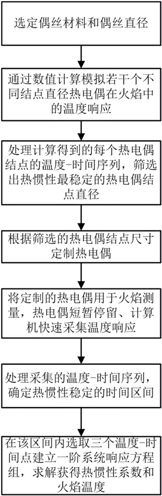
Dynamic temperature measuring method for correcting thermal inertia drift of system thermocouple
A dynamic temperature measurement and thermocouple technology, applied in the field of measurement, can solve the problem of thermocouple inertia coefficient drift and other problems
- Summary
- Abstract
- Description
- Claims
- Application Information
AI Technical Summary
Problems solved by technology
Method used
Image

Examples
Embodiment Construction
[0061] The specific embodiments of the present invention will be further described below in conjunction with the accompanying drawings. It is to be noted that these examples of embodiments are provided to help understanding of the present invention. However, the embodiments of the present invention are not limited thereto.
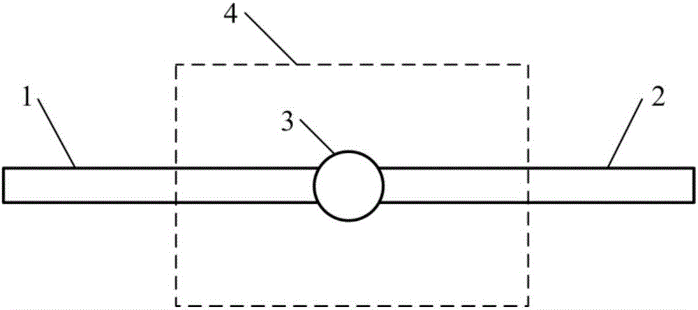
[0062] The first step is to establish a geometric model and a mathematical model for thermocouple dynamic temperature measurement according to the measured soot flame. The simulated flame is at temperature T s , the velocity is u s , diameter is D s cylindrical airflow. Generally, T is preset during calculation s higher than the measured flame temperature (T s =1800K), u s Close to the measured flame velocity (v s =1m / s), D s Greater than 10 times the thermocouple junction diameter (D s =0.02m), the thermocouple wires are butted (two wires are on the same straight line, and the length of each wire is 50mm), the node is located on the axis of the ...
PUM
 Abstract
Description
Claims
Application Information