
Power Factor Correction Converter Average Current Control Method and Device

A power factor correction and current control technology, applied in the field of PFC converter average current control method and device, can solve the problems of unstable operating frequency, slow transient response speed, difficult design of output filter, etc. The effect of improving the state performance, improving the PF value, and improving the efficiency

Active Publication Date: 2018-07-31
SOUTHWEST JIAOTONG UNIV
View PDF3 Cites 0 Cited by
  • Summary
  • Abstract
  • Description
  • Claims
  • Application Information

AI Technical Summary

Problems solved by technology

The power factor of the current hysteresis control PFC converter is high and the response speed is fast, but the operating frequency is not fixed, and the output filter is difficult to design; the power factor of the peak current control PFC converter is low, which cannot meet the total harmonic distortion (Total Harmonic Distortion) , THD) requirements, and the control method is quite sensitive to noise; the average current control PFC converter has a high power factor and small THD, is not sensitive to noise, and can be applied to the continuous conduction mode of the inductor current (continuous conduction mode, CCM) and discontinuous conduction mode (discontinuous conduction mode, DCM)
However, the average current control uses two PI compensators, so the transient response of the average current control is slower

Method used


Image

  • Power Factor Correction Converter Average Current Control Method and Device
  • Power Factor Correction Converter Average Current Control Method and Device
  • Power Factor Correction Converter Average Current Control Method and Device

Examples


Embodiment 1

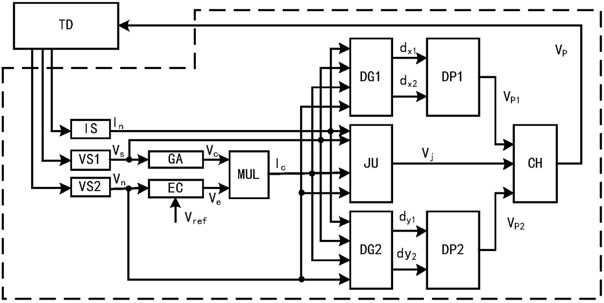
[0029] figure 1 It is shown that a specific embodiment of the present invention is: a PFC converter average current control method and its device, including a current detection circuit IS, a first voltage detection circuit VS1, a second voltage detection circuit VS2, a compensator EC, and an amplifier GA , multiplier MUL, first duty ratio generator DG1, second duty ratio generator DG2, first pulse width modulator DP1, second pulse width modulator DP2, judger JU and selector CH; current detection The circuit IS is used to obtain the output current information I of the rectifier bridge n , the first voltage detection circuit VS1 is used to obtain the output voltage information V of the rectifier bridge s , The second voltage detection circuit VS2 is used to obtain the output voltage information V of the converter TD n , the compensator EC is used to generate the error signal V e , the judging unit JU is used to generate the selection signal V j , the judgment circuit works i...

Embodiment 2

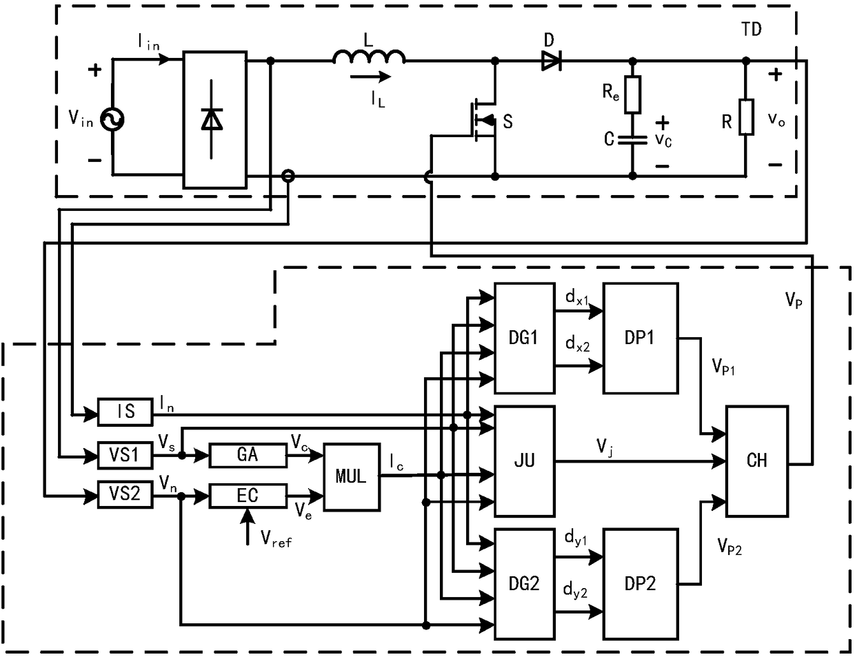
[0045] Such as Figure 10 As shown, this example is basically the same as the first example, except that the converter TD controlled in this example is a Buck-boost PFC converter.

[0046] In addition to the PFC converters in the above embodiments, the present invention can also be used in PFC converter topologies such as flyback PFC converters, half-bridge PFC converters, and full-bridge PFC converters.


PUM


Abstract

A power factor correction converter average current control method and its device. At the beginning of each switching cycle, the output voltage of the converter and the voltage reference value are passed through a compensator to generate a signal Ve, and the output voltage of a rectifier bridge is passed through an amplifier to obtain a signal Ve Vc, the signal Ic is obtained by passing Ve and Vc through the multiplier; the output voltage and output current of the rectifier bridge, the output voltage and Ic of the converter are sent to the duty cycle generator, and the signals dx and dy are obtained by calculating the duty cycle algorithm. Then, the control sequence VP1 and VP2 is generated through the pulse width modulator; the output voltage and output current of the rectifier bridge, the output voltage and Ic of the converter are sent to the judge and selector, and VP1 or VP2 is selected; the conduction of the switch tube of the converter is controlled on and off. The invention is applicable to various topologies of power factor correction converters. In wide input voltage and wide load ranges, the converter maintains good power factor correction function and high work efficiency, and has fast load transient response speed.

Description

technical field [0001] The invention relates to a control method and a realization device of a power factor correction (Power Factor Correction, PFC) converter, which belongs to the field of power electronic equipment, in particular to a PFC converter mean value current control method and a device thereof. Background technique [0002] With the development of power electronic technology, the application of power electronic devices is becoming more and more extensive. Power electronic devices contain various nonlinear devices and energy storage devices. When they are directly connected to the public grid, the grid current will be distorted, that is, a large number of harmonics will be injected into the grid, which seriously affects the power supply quality and The normal operation of other electrical equipment may even cause damage to electrical equipment. [0003] In order to ensure the normal power supply of the public grid, PFC technology needs to be used, that is, a filt...

Claims


Application Information

Patent Timeline
Patent Type & Authority Patents(China)
IPC IPC(8): H02M1/42H02M7/04
CPCH02M1/42H02M7/04H02M1/0058Y02B70/10
Inventor 周国华刘啸天冷敏瑞徐顺刚
Owner SOUTHWEST JIAOTONG UNIV
Learn More