Desulfurized flue gas dehumidification and water recovery system and method

A water recovery and flue gas technology, which is applied in chemical instruments and methods, separation methods, lighting and heating equipment, etc., can solve the problems that the latent heat of water vapor cannot be recovered, the thermal efficiency of the boiler system is affected, and the solution dehumidification system is complicated, and the structure is compact. , the effect of saving floor space and high equipment integration

Inactive Publication Date: 2017-01-04
SHANDONG UNIV
View PDF6 Cites 12 Cited by
  • Summary
  • Abstract
  • Description
  • Claims
  • Application Information

AI Technical Summary

Problems solved by technology

Conventional solution regeneration consumes the heat provided by the outside to evaporate and discharge the water in the dilute solution. The concentration of the solution increases, and the heat provided by the outside is converted into latent heat of water vapor. Due to the heat transfer process, the boiling point of water vapor is lower than the temperature of the heat source required for regeneration, so The latent heat of water vapor cannot be recovered for heating the dilute solution, thus affecting the thermal efficiency of the entire boiler sys

Method used


Image

  • Desulfurized flue gas dehumidification and water recovery system and method
  • Desulfurized flue gas dehumidification and water recovery system and method

Examples


Embodiment 1

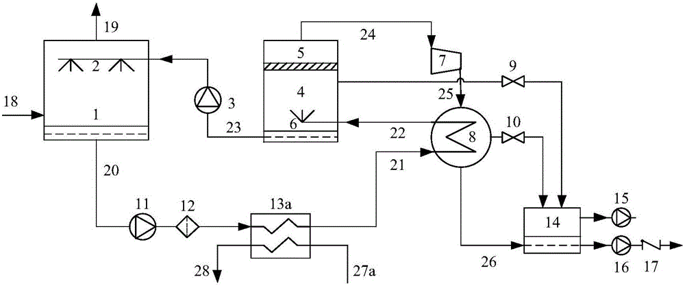
[0053] Embodiment 1: refer to figure 1 As shown, a low-energy desulfurization flue gas dehumidification and water recovery device based on vapor compression heat recovery includes a dehumidifier 1, a first solution pump 3, a flash evaporator 4, a steam compressor 7, a heat exchanger 8, a first electromagnetic Valve 9, second solenoid valve 10, second solution pump 11, solution filter 12, solution-water heat exchanger 13a, pressure regulator reservoir 14, vacuum pump 15, condensate booster pump 16, condensate check valve 17 and connecting pipeline.

[0054] The solution outlet of the dehumidifier 1 is communicated with the solution inlet of the solution-water heat exchanger 13a through the second solution pump 11 and the solution filter 12, and the solution outlet of the solution-water heat exchanger 13a is communicated with the solution inlet of the condensing heat exchanger 8 , the solution outlet of the condensing heat exchanger 8 communicates with the solution spraying dev...

Embodiment 2

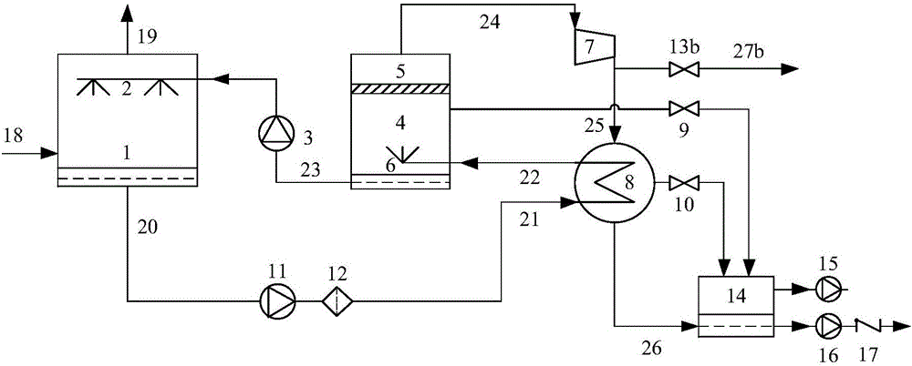
[0062] Embodiment 2: refer to figure 2 As shown, a low-energy desulfurization flue gas dehumidification and water recovery device based on vapor compression heat recovery includes a dehumidifier 1, a first solution pump 3, a flash evaporator 4, a steam compressor 7, a heat exchanger 8, a first electromagnetic Valve 9, second solenoid valve 10, second solution pump 11, solution filter 12, flow regulating valve 13b, steady pressure liquid reservoir 14, vacuum pump 15, condensed water booster pump 16, condensed water one-way valve 17 and connection pipeline.

[0063] The solution outlet of the dehumidifier 1 communicates with the solution inlet of the condensing heat exchanger 8 through the second solution pump 11 and the solution filter 12, and the solution outlet of the condensing heat exchanger 8 is connected with the solution spraying device 6 extending into the lower end of the flasher 4 inner chamber. The solution outlet of the flash evaporator 4 communicates with the sol...


PUM


Abstract

The invention discloses a desulfurized flue gas dehumidification and water recovery system and method. The system comprises a dehumidifier, a heat exchanger, a flash evaporator and a steam compressor. A moisture absorption solution in the dehumidifier makes contact with desulfurized flue gas, water in the desulfurized flue gas is removed, and a dilute solution is obtained; the dilute solution flowing out of the dehumidifier enters the heat exchanger for heat exchange, and a high-temperature dilute solution is obtained; the high-temperature dilute solution flowing out of the heat exchanger enters the flash evaporator for flash evaporation, a regenerated moisture absorption solution and low-pressure steam are obtained, the moisture absorption solution enters the dehumidifier, the desulfurized flue gas is dehumidified, the low-pressure steam is compressed through the steam compressor and then enters the heat exchanger, and the dilute solution is heated. After the steam generated in the flash evaporation process is compressed to increase the boiling point, a heating heat source used as the dilute solution is condensed and subjected to heat release, heat needed by regeneration of the dilute solution does not need to be supplied by the exterior, and the energy consumption and operating cost of the desulfurized flue gas solution dehumidification system are reduced to the maximum degree.

Description

technical field [0001] The invention relates to the field of boiler flue gas treatment, in particular to a desulphurization flue gas dehumidification and water recovery system and method. Background technique [0002] Power, metallurgy, iron and steel, and chemical processes usually produce a large amount of moisture-containing gas. The volume content of water vapor in the flue gas discharged from gas-fired boilers can reach about 15%. The volume composition of steam can also reach more than 10% of the total amount of flue gas. These humid gases are basically in a saturated state. When they are directly discharged at the outlet of the chimney, the water vapor will condense into water droplets, thus forming "chimney rain" and "white smoke". And other environmental problems, and the formation of acid inside the chimney to cause corrosion. In addition, the direct discharge of wet gas also causes a waste of water resources. [0003] At present, the solutions to the "chimney ra...

Claims


Application Information

Patent Timeline
IPC IPC(8): B01D53/26B01D53/14B01D53/18F23J15/00
CPCB01D53/263B01D53/1425B01D53/1493B01D53/18B01D2253/10F23J15/00
Inventor 徐震董勇
Owner SHANDONG UNIV
Why Eureka
Try Eureka