Control method of guillotine shear hydraulic system

A technology of a hydraulic system and a control method, applied in the field of hydraulic presses, can solve the problems of bulky and heavy equipment, reduced equipment stability, and high production costs, and achieves the effects of sensitive system action, compact structure and fewer pipelines

Active Publication Date: 2017-01-04
安徽省华夏机床制造有限公司
View PDF14 Cites 4 Cited by
  • Summary
  • Abstract
  • Description
  • Claims
  • Application Information

AI Technical Summary

Problems solved by technology

[0007] In view of the complex structure of the hydraulic system of the existing gate-type shearing machine, which leads to bulky and heavy equipment, high production costs, reduced equipment stability, and inability to adapt to various operating environments, the present invention provides a gate-type shearing machine The control method of the hydraulic system. Compared with the existing hydraulic system, the structure of this system is greatly simplified, which reduces the production cost. Maintenance

Method used


Image

  • Control method of guillotine shear hydraulic system

Examples


Embodiment 1

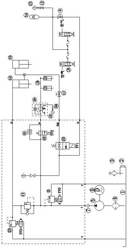
[0049] Such as figure 1 As shown, the hydraulic system of a gate-type shearing machine in this embodiment includes an oil tank 1, an oil pump 5, an electromagnetic overflow valve I8, an on-off valve 10, a sequence valve 11, an accumulator 14, a return cylinder 15, and a pressure cylinder 16. Main oil cylinder 18, auxiliary oil cylinder 19 and check valve II 21. Wherein, the piston rods of the main oil cylinder 18 and the auxiliary oil cylinder 19 are connected to the knife rest, and are used to drive the knife rest to move downward to complete the shearing of the plate. The auxiliary oil cylinder 19 adopts a plunger cylinder, and the return oil cylinder 15 is connected with the knife rest. It is used to drive the tool holder upward to make a return movement.

[0050] The oil tank 1 is equipped with a liquid level gauge 2 to monitor the liquid level in real time to prevent insufficient hydraulic oil and to replenish it in time. The oil tank 1 communicates with the air through ...


PUM


Abstract

The invention discloses a control method of a guillotine shear hydraulic system and belongs to the technical field of hydraulic machines. The control method controls the hydraulic system to finish system unloading stand-by state control of a plate shear, material preloading control, shearing control, return stroke control, tool rest shear angle decrease or increase control, energy accumulator charging control and oil cylinder charging control through sequential control of an electromagnetic relief valve I, a switching valve, a two-position two-way electromagnetic valve and an electromagnetic relief valve II in combination with a check valve I and a check valve II. Compared with the existing hydraulic system, the guillotine shear hydraulic system has the advantages that the the structure greatly simplified and the production cost is reduced. The control method enables the system to operate stably and can meet various working operation requirements. The material pressing action can be controlled independently and the pressure is controllable, and it is convenient to overhaul and maintain.

Description

technical field [0001] The invention belongs to the technical field of hydraulic machines, and more specifically relates to a control method for a hydraulic system of a gate shearing machine. Background technique [0002] The plate shearing machine is a machine that uses one blade to make a reciprocating linear motion relative to the other blade to cut the plate. It uses the moving upper blade and the fixed lower blade to apply shear to metal plates of various thicknesses with a reasonable blade gap. Force, so that the plate is broken and separated according to the required size. The shearing machine is divided into mechanical shearing machine and hydraulic shearing machine. The thickness of the steel plate that the mechanical shearing machine can cut is generally less than 10mm, while the hydraulic shearing machine is mostly used to cut the steel plate above 6mm. Hydraulic shearing machine is divided into pendulum shearing machine and gate shearing machine. Compared with p...

Claims


Application Information

Patent Timeline
Patent Type & Authority Applications(China)
IPC IPC(8): B23D15/14B23D15/08F15B1/02F15B11/20F15B13/07F15B19/00F15B20/00F15B21/04
CPCB23D15/08B23D15/14F15B1/024F15B11/20F15B13/07F15B19/00F15B20/007F15B21/041F15B2013/006F15B2211/205F15B2211/212F15B2211/405F15B2211/615F15B2211/857
Inventor 吴金福夏克周
Owner 安徽省华夏机床制造有限公司
Why Eureka
Try Eureka