
Method ensuring deformation steel plate to smoothly pass crop shear swing roller-way

A technology of cutting head shears and swinging rollers, which is applied to the attachments of shearing machines, shearing devices, metal processing, etc., can solve the problems of easy damage of auxiliary equipment, deformation of guard plates, and difficulties in handling accidents, and achieve reduction Accident time and spare parts cost, enhanced impact resistance and guidance capabilities, and the effect of improving product competitiveness

Active Publication Date: 2017-01-04
ANGANG STEEL CO LTD
View PDF7 Cites 0 Cited by
  • Summary
  • Abstract
  • Description
  • Claims
  • Application Information

AI Technical Summary

Problems solved by technology

The first three roller guards do not have enough space for lifting operations and there is no place to hang the lifting equipment (the swinging roller is 350mm away from the bottom of the reducer). It is very difficult to deal with accidents. Even if there are spare parts, they cannot be replaced, and accidents often occur The guard plate has the risk of being impacted and deformed, and this part must be protected by the guard plate. Because the roller table swings up and down, the steel plate passing through it is very easy to get the steel plate into the roller table, and it is more difficult to handle.
[0003] The 3800 production line cutting shears cannot pass through the deformed steel plate with a width of more than 4200mm, scratching occurs, and the impact damages the equipment. The lower surface of the sheared steel plate and the ancillary equipment of the body are easily damaged

Method used


Image

  • Method ensuring deformation steel plate to smoothly pass crop shear swing roller-way
  • Method ensuring deformation steel plate to smoothly pass crop shear swing roller-way
  • Method ensuring deformation steel plate to smoothly pass crop shear swing roller-way

Examples


Embodiment Construction

[0019] The specific embodiment of the present invention is further described below in conjunction with accompanying drawing:

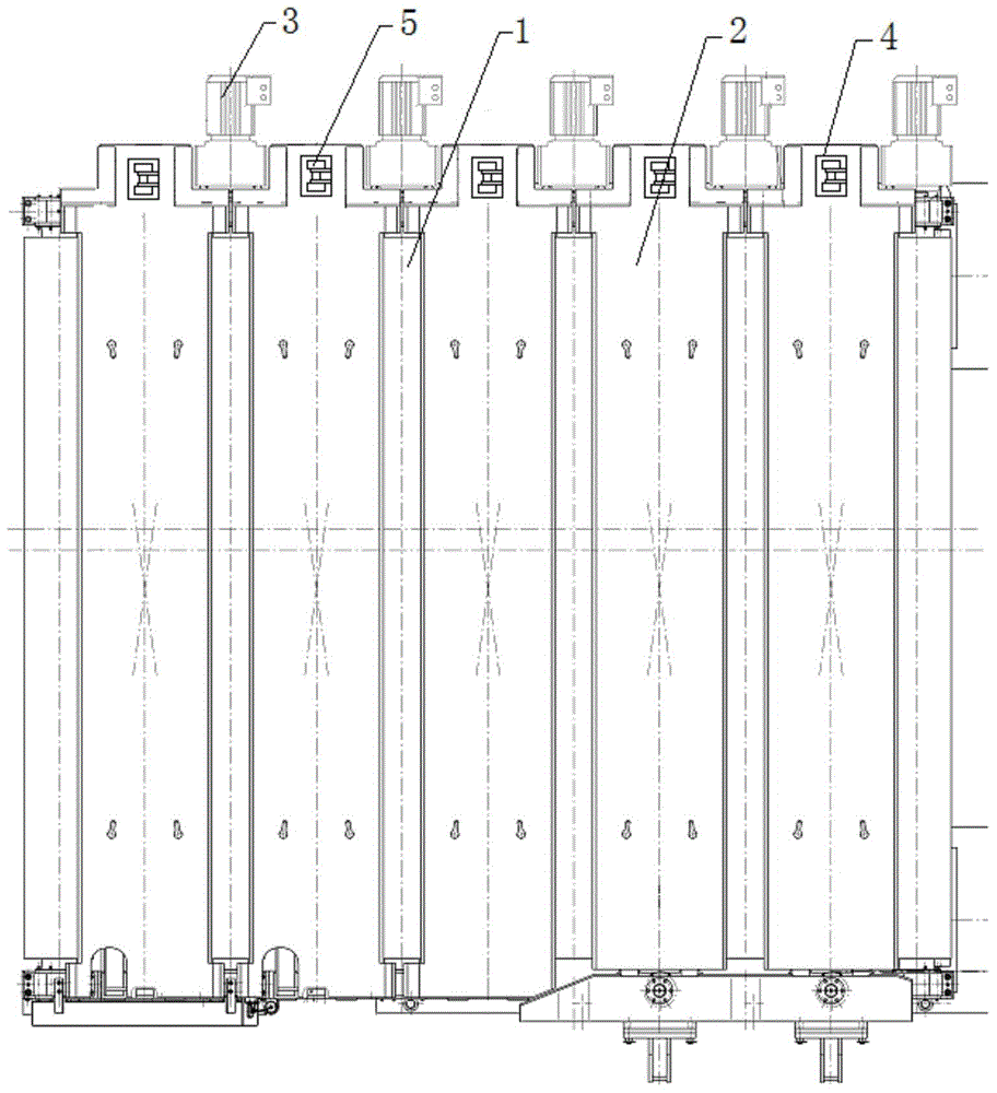
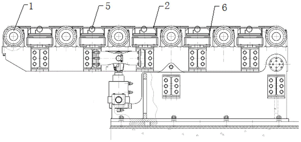
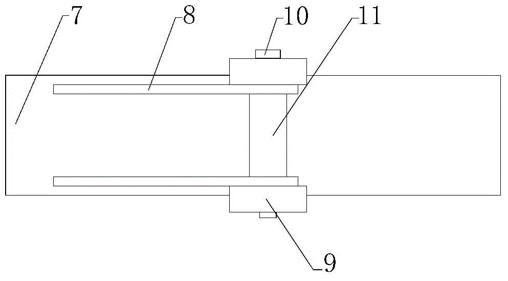
[0020] Such as Figure 1-Figure 2 As shown in the figure, a guide device is installed under the roller guard plate of the swing roller table of the crop shear. The guide device is installed under the adjacent roller guard plate on the side of the geared motor. The rollers in the guide device are at the same height as the swing roller table, and the deformed steel plate It is jointly supported and guided by the swinging roller table and the guide device, so that the roller table guard plate does not contact the deformed steel plate.

[0021] A oscillating roller table for crop shears to ensure the smooth passage of deformed steel plates, including a oscillating roller table 1 and a roller table guard 2, the roller table 1 is driven to rotate by a reduction motor 3, and the roller table between the adjacent roller table 1 on the side of the reduction mot...


PUM


Abstract

The invention relates to a method ensuring a deformation steel plate to smoothly pass a crop shear swing roller-way; guide units are added below a roller-way guard boards of the crop shear swing roller-way, and arranged below the roller-way guard boards adjacent to a deceleration motor; a roller in the guide unit and the swing roller-way are consistent in height; the deformation steel plate is commonly supported and guided by the swing roller-way and the guide units, so the roller-way guard boards cannot make contact with the deformation steel plate. The method can fully utilize a conventional design system structure, so the conventional structure does not to change for a bit; the guide units are added so as to prevent the roller-way guard boards from making contact with the deformation steel plate, and thus preventing the steel plate from entering the roller-way. The roller-way guard board crashproof and guiding ability can be enhanced; the steel plate can smoothly pass the roller-way without scrapping and bumping into the roller-way guard boards, thus ensuring the shear steel plate bottom surface quality, and the body auxiliary device cannot be damaged, thus reducing accident time and spare part cost.

Description

technical field [0001] The invention relates to crop shear equipment, in particular to a method for ensuring that a deformed steel plate smoothly passes through a swing roller table of the crop shear. Background technique [0002] The oscillating roller table of the thick plate cutting head shear is designed in the scissors body. The six groups of roller tables are integrated, and the middle and front parts are operated by two hydraulic cylinders to realize the up and down movement of the roller table group. The first three roller guards do not have enough space for lifting operations and there is no place to hang the lifting equipment (the swinging roller is 350mm away from the bottom of the reducer). It is very difficult to deal with accidents. Even if there are spare parts, they cannot be replaced, and accidents often occur The guard plate has the risk of being impacted and deformed, and this part must be protected by the guard plate. Because the roller table swings up an...

Claims


Application Information

Patent Timeline
Patent Type & Authority Applications(China)
IPC IPC(8): B23D33/02B23Q7/05
Inventor 侯盈赵立军肖争光刘晓松卜凯军
Owner ANGANG STEEL CO LTD
Learn More