
Apparatus and method for producing oil by means of coal pyrolysis

A technology of coal pyrolysis and pyrolysis chamber, which is applied in the petroleum industry, the manufacture of combustible gas, and the preparation of liquid hydrocarbon mixtures. It can solve the problems of reduced production capacity, complicated process, and low oil production rate, and achieve stable operation. , conducive to the effect of large-scale

Active Publication Date: 2017-01-04
SINOPEC NINGBO ENG +2
View PDF6 Cites 2 Cited by
  • Summary
  • Abstract
  • Description
  • Claims
  • Application Information

AI Technical Summary

Problems solved by technology

[0003] In the existing coal direct liquefaction technology, the reaction pressure of the reactor is as high as 17MPa-30Mpa, and the hydrogen consumption is as high as 6%-10%. The process is complicated and the investment cost is high
In the process, not only a large amount of new hydrogen needs to be added, but also circulating oil is required as a hydrogen supply solvent, the production capacity of the device is reduced, the product composition of the liquefaction reactor is complicated, the solid-liquid two-phase separation is difficult, and the oil production rate is low

Method used


Image

  • Apparatus and method for producing oil by means of coal pyrolysis
  • Apparatus and method for producing oil by means of coal pyrolysis
  • Apparatus and method for producing oil by means of coal pyrolysis

Examples


Embodiment Construction

[0031] The present invention will be further described in detail below in conjunction with the accompanying drawings and embodiments.

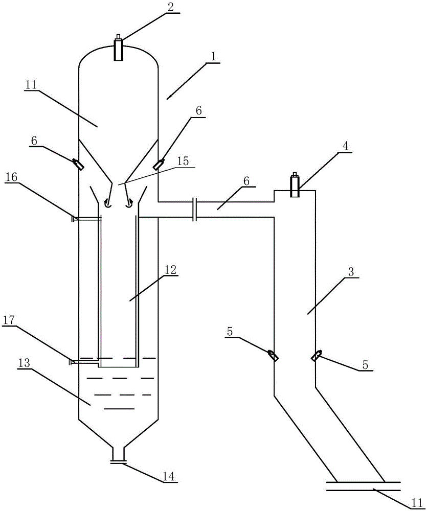
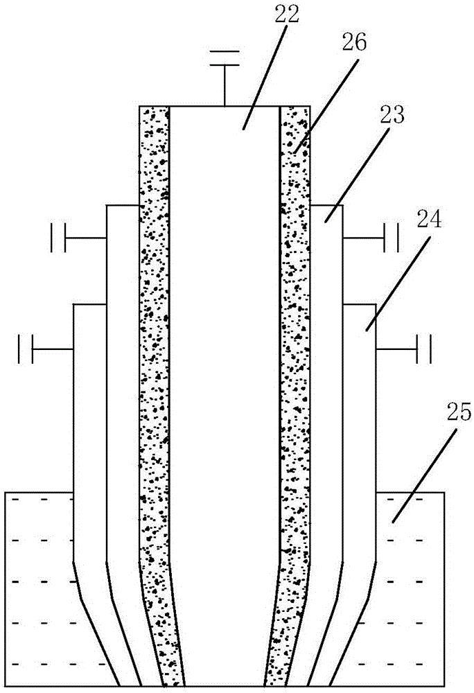
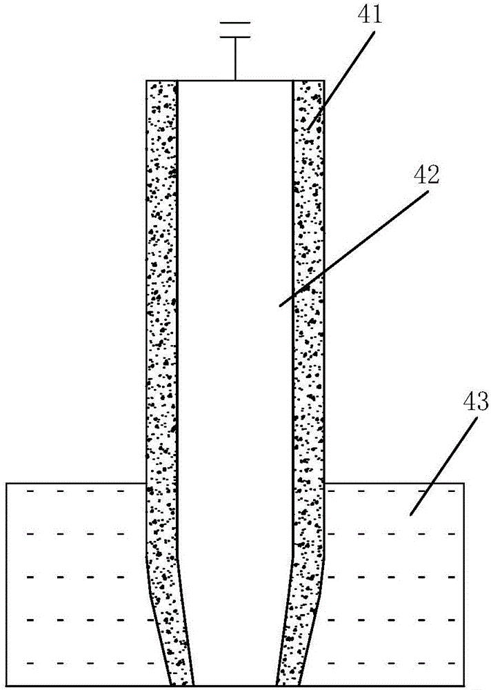
[0032] like Figure 1 to Figure 3 As shown, the coal pyrolysis oil production device includes a gasifier 1 and a pyrolysis chamber 3 that are connected to each other.

[0033] The gasification furnace 1 includes a gasification chamber 11 , a downcomer 12 and a quenching chamber 13 sequentially from top to bottom. The gasification chamber 11 is a hot-wall reactor structure, with a gasification nozzle 2 at the top and a conical structure at the bottom, and the outlet 15 at the bottom communicates with the inlet of the downcomer 12 .

[0034] The downcomer 12 is connected with a cooling water pipe 16 through which quenching water is passed into the surface of the downcomer 12 to form a water film on the inner wall of the downcomer to protect the downcomer. The entrance of the downcomer 12 is a flared bell mouth to facilitate the receiving of ma...


PUM


Abstract

The invention relates to an apparatus and a method for producing oil by means of coal pyrolysis. The apparatus comprises a gasification furnace. A gasification nozzle is arranged on the top of the gasification furnace, a gasification chamber is arranged on the upper portion of the gasification furnace, a chilling chamber is arranged at the bottom of the gasification chamber, a bottom outlet of the gasification chamber is communicated with the chilling chamber via a downcomer, and a residue outlet is formed in the bottom of the gasification furnace. The apparatus is characterized in that the gasification furnace is connected with a pyrolysis chamber by a synthesis gas delivery passage, a coal nozzle is arranged on the top of the pyrolysis chamber, temperature reducing nozzles are arranged in the middle of the pyrolysis chamber, and a product outlet is formed in the bottom of the pyrolysis chamber. The apparatus and the method have the advantages that coal gasification and coal hydrogenation requirements can be simultaneously met without additional hydrogen sources; a gasification system and a pyrolysis system are independent from each other, accordingly, the apparatus and the method are favorable for stable running of reactors, and the apparatus can be advantageously enlarged.

Description

technical field [0001] The invention relates to chemical equipment, in particular to a coal pyrolysis oil production device and a coal pyrolysis oil production method. Background technique [0002] The direct coal hydrogenation process mainly includes coal crushing and drying, coal slurry preparation, hydrogenation liquefaction, solid-liquid separation, gas purification, fractionation and refining of liquid products, and hydrogen production. The main process is: under high temperature and high pressure, the coal in the high-concentration coal slurry undergoes pyrolysis, undergoes hydrogenation and decomposition under the action of a catalyst, and finally becomes a stable liquid molecule. During the liquefaction process, the coal slurry made of coal, catalyst and cycle oil is mixed with the hydrogen produced and sent to the reactor. In the liquefaction reactor, coal first undergoes a pyrolysis reaction to generate free radical "fragments", and the unstable free radical "frag...

Claims


Application Information

Patent Timeline
Patent Type & Authority Applications(China)
IPC IPC(8): C10G1/06C10J3/46C10J3/48C10J3/72
CPCC10G1/06C10J3/46C10J3/48C10J3/72C10J2300/093C10J2300/0943C10J2300/0959C10J2300/0976
Inventor 王鲁杰郭强杨松峰赵国忠李克海李峰吴德民刘文胡宪严东
Owner SINOPEC NINGBO ENG
Learn More