Multilayer composite coating for cutter, cutter and preparation method of cutter
A multi-layer composite and coating technology, applied in the field of cutting tools and their preparation, multi-layer composite coating, can solve the problems of large strain energy and difficult to form, and achieve the effect of low equipment requirements, improved hardness and high hardness
- Summary
- Abstract
- Description
- Claims
- Application Information
AI Technical Summary
Problems solved by technology
Method used
Image
Examples
Embodiment 1
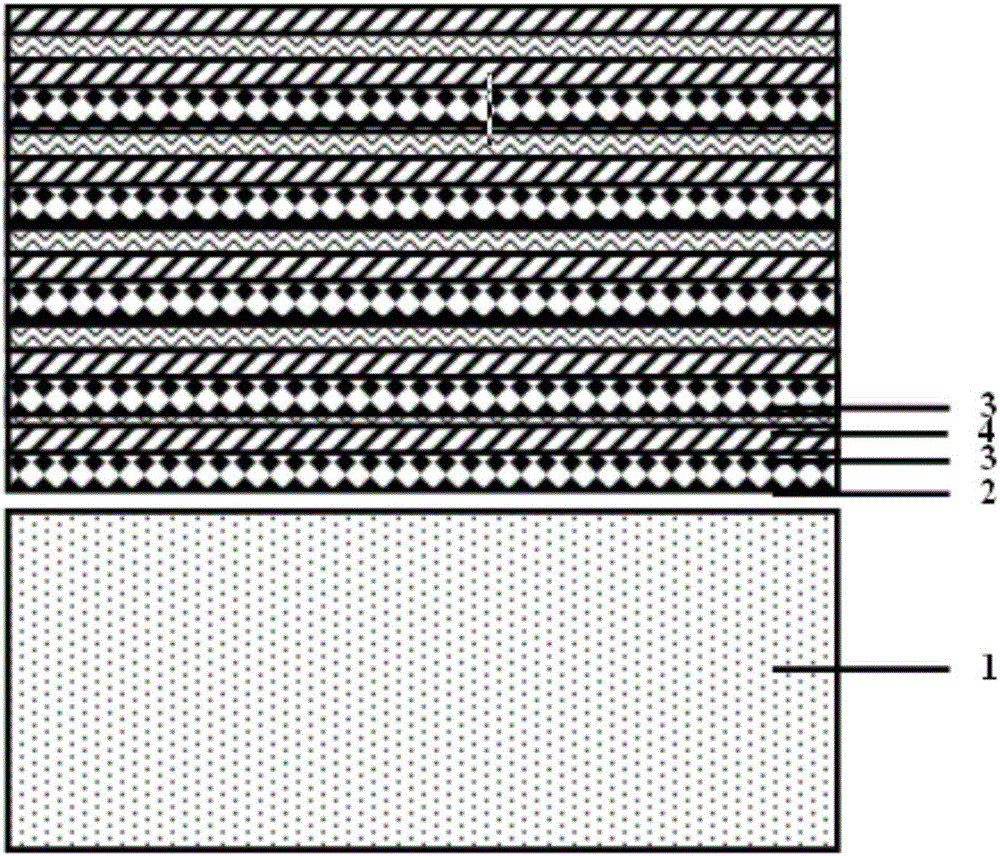
[0031]Deposition by physical vapor deposition method (see: Correlation between arc evaporation of Ti-Al-N coatings and corresponding Ti0.50Al0.50 target types, Surface & Coatings Technology, 275 (2015) 309-315)), using CrAl target, CrZr target and Zr target alternately Deposition "Cr 1-x al x N layer 2 to Cr 1-y Zr y N layer 3 to ZrN layer 4 to Cr 1-y Zr y Periodic variation trend of Cr in N layer 3" 1-x al x N / Cr 1-y Zr y N / ZrN / Cr 1- y Zr y N multi-layer composite coating, Cr 1-x al x The Al content in the N layer is controlled at 0≤X1-y Zr y The Zr content of the N layer is controlled at 0.30≤y≤0.70, Cr 1-x al x N layer 2, Cr 1-y Zr y N layer 3, ZrN layer 4 and Cr 1-y Zr y The single layer thickness of the N layer 3 is 3nm, 8nm, 4nm, 9nm in turn, after 250 cycles until the total thickness of the coating is 6.0 μm.
Embodiment 2
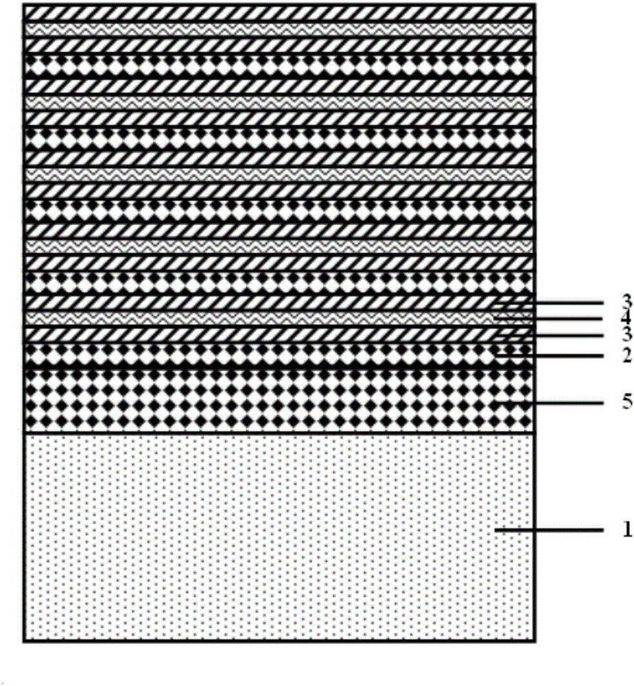
[0033] By physical vapor deposition method (see: Correlation between arc evaporation of Ti-A1-N coatings and corresponding Ti 0.50 al 0.50 target types, Surface & Coatings Technology, 275 (2015) 309-315) deposition, first depositing Cr on the tool substrate 1 using a CrAl target 1-x al x N transition layer 5, again in Cr 1-x al x On the N transition layer 5, the physical vapor deposition process is used to deposit "Cr 1- x al x N layer 2 to Cr 1-y Zr y N layer 3 to ZrN layer 4 to Gr 1-y Zr y Periodic variation trend of Cr in N layer 3" 1-x al x N / Cr 1-y Zr y N / ZrN / Cr 1-y Zr y N multi-layer composite coating, Cr 1-x al x N layer 2 The Al content in is controlled at 0≤X≤0.70, Cr 1-y Zr y The Zr content of the N layer is controlled at 0.30≤y≤0.70, the Cr 1-x al x N layer 2, Cr 1-y Zr y N layer 3, ZrN layer 4 and Cr 1-y Zr y The single-layer thickness of the N layer 3 is 2nm, 7nm, 3nm, and 10nm in sequence, and after 450 cycles, the total thickness of the...
Embodiment 3
[0035] By physical vapor deposition method (see: Correlation between arc evaporation of Ti-Al-N coatings and corresponding Ti 0.50 al 0.50 target types, Surface & Coatings Technology, 275 (2015) 309-315) deposition, deposition of "Cr 0.48 al 52 N layer 2 to Cr 0.50 Zr 0.50 N layer 3 to ZrN layer 4 to Cr 0.50 Zr 0.50 Periodic variation trend of Cr in N layer 3" 0.48 al 52 N / Cr 0.50 Zr 0.50 N / ZrN / Cr 0.50 Zr 0.50 N multilayer composite coating, where Cr 0.48 al 52 N layer 2, Cr 0.50 Zr 0.50 N layer 3, ZrN layer 4, Cr 0.50 Zr 0.50 The thickness of the N layer 3 is 6nm, 5nm, 4nm, 5nm in turn, after 150 cycles until the total thickness of the coating is 3.0 μm.
[0036] Cr prepared by the present invention 0.48 al 52 N / Cr 0.50 Zr 0.50 N / ZrN / Cr 0.50 Zr 0.50 The N multilayer composite coating has a single-phase cubic structure, and was obtained by the nanoindentation method (see: Correlation between arc evaporation of Ti-A1-Ncoatings and corresponding Ti-A1-Ncoa...
PUM
| Property | Measurement | Unit |
|---|---|---|
| Thickness | aaaaa | aaaaa |
| Thickness | aaaaa | aaaaa |
| Hardness | aaaaa | aaaaa |
Abstract
Description
Claims
Application Information
 - R&D Engineer
- R&D Manager
- IP Professional
- Industry Leading Data Capabilities
- Powerful AI technology
- Patent DNA Extraction
Browse by: Latest US Patents, China's latest patents, Technical Efficacy Thesaurus, Application Domain, Technology Topic, Popular Technical Reports.
© 2024 PatSnap. All rights reserved.Legal|Privacy policy|Modern Slavery Act Transparency Statement|Sitemap|About US| Contact US: help@patsnap.com


