Write circuit structure for self-transfer torque magnetic random access memory

A spin torque transfer, random access memory technology, applied in static memory, digital memory information, information storage and other directions, can solve the problem of repeated writing of data bits

Active Publication Date: 2017-01-04
CETHIK GRP +1
View PDF4 Cites 2 Cited by
  • Summary
  • Abstract
  • Description
  • Claims
  • Application Information

AI Technical Summary

Problems solved by technology

[0004] The purpose of the present invention is to provide a write circuit structure of spin torque transfer magnetic random access memory, to solve the problem of repeated writing of most of the data bits in the prior

Method used


Image

  • Write circuit structure for self-transfer torque magnetic random access memory
  • Write circuit structure for self-transfer torque magnetic random access memory
  • Write circuit structure for self-transfer torque magnetic random access memory

Examples


Embodiment approach 1

[0032] Embodiment 1, such as Figure 6 As shown, the control unit includes a NOR gate and an AND gate.

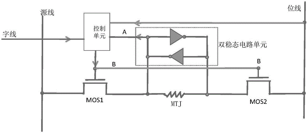
[0033] Such as image 3 , 6 As shown, the control unit of this embodiment includes a NOR gate and an AND gate, the two inputs of the NOR gate are respectively connected to the bit line and point A, one input terminal of the AND gate is connected to the output of the NOR gate, and the other The input end is connected to the word line, and the output of the AND gate is connected to point B, which is the output of the control unit.

[0034]Under the control of the word line, when the control signal of the write operation is input on the word line, the control unit first judges whether the content stored in the memory cell (that is, the potential at the first end of the bistable circuit unit) is equal to the bit line, and if they are equal , the potential of point B is "1", then turn on MOS1 and MOS2, allowing data to be written and updated; if the stored content is differen...

Embodiment approach 2

[0041] Embodiment 2, such as Figure 7 As shown, the control unit includes an XOR gate and an AND gate.

[0042] Such as Figure 4 , Figure 7 As shown, the control unit of this embodiment includes an XOR gate and an AND gate, the two inputs of the XOR gate are respectively connected to the source line and point A, one input terminal of the AND gate is connected to the output of the XOR gate, and the other The input end is connected to the word line, and the output of the AND gate is connected to point B, which is the output of the control unit.

[0043] Under the control of the word line, when the control signal of the write operation is input on the word line, the control unit first judges whether the content stored in the memory cell is equal to the data to be written (source line), if they are equal, the potential of point B is " 0", MOS1 and MOS2 are not turned on, and this write operation is shielded; if the stored content is different from the data to be written, the...


PUM


Abstract

The invention discloses a write circuit structure for a self-transfer torque magnetic random access memory. The write circuit structure for the self-transfer torque magnetic random access memory comprises a magnetic tunnel junction, a source line, a bit line, a word line, a first switching tube, a second switching tube, a control unit and a bistable circuit unit, wherein a free layer of the magnetic tunnel junction is connected with a drain of the first switching tube; a reference layer of the magnetic tunnel junction is connected with a source of the second switching tube; the source of the first switching tube is connected with the source line; the drain of the second switching tube is connected with the bit line; a first end of the bistable circuit unit is connected with the free layer of the magnetic tunnel junction and the input of the control unit; a second end of the bistable circuit unit is connected with the reference layer of the magnetic tunnel junction; an input end of the control unit is connected with each of the word line, the source line and the bit line; a first end of the bistable circuit unit and an output end of the control unit are connected with the grid of the first switching tube and that of the second switching tube. According to the write circuit structure, repeated writing action can be avoided, and the purposes of reducing the writing power consumption of an MRAM and the dynamic power consumption of a chip are achieved.

Description

technical field [0001] The invention relates to the technical field of nonvolatile memory, in particular to a write circuit structure of a spin torque transfer magnetic random access memory. Background technique [0002] The spin torque transfer magnetic random access memory (STT-MRAM) is a kind of non-volatile memory, and its storage structure adopts MTJ magnetic tunnel junction, such as figure 1 As shown, the middle layer is called the barrier layer, and the upper and lower layers are the free layer and the reference layer respectively. When writing data "0", the current flows from the reference layer through the free layer to make the MTJ (magnetic tunnel junction) flip to an antiparallel state; when writing data "1", the current flows from the free layer through the reference layer to make the MTJ (magnetic tunnel junction) knot) flips to the parallel state. To flip the magnetic tunnel junction, a certain voltage must be maintained at both ends of the magnetic tunnel j...

Claims


Application Information

Patent Timeline
IPC IPC(8): G11C11/16
CPCG11C11/1675G11C11/16
Inventor 毛欣
Owner CETHIK GRP
Why Eureka
Try Eureka