
Selective removal of boron doped carbon hard mask layer

A film and plasma technology, applied in the direction of discharge tubes, electrical components, circuits, etc., can solve the problem of difficult removal of the hard mask layer

Active Publication Date: 2017-01-04
LAM RES CORP
View PDF6 Cites 1 Cited by
  • Summary
  • Abstract
  • Description
  • Claims
  • Application Information

AI Technical Summary

Problems solved by technology

However, hard mask layers are also becoming increasingly difficult to remove with typical plasma lift-off processes

Method used


Image

  • Selective removal of boron doped carbon hard mask layer
  • Selective removal of boron doped carbon hard mask layer
  • Selective removal of boron doped carbon hard mask layer

Examples


Embodiment Construction

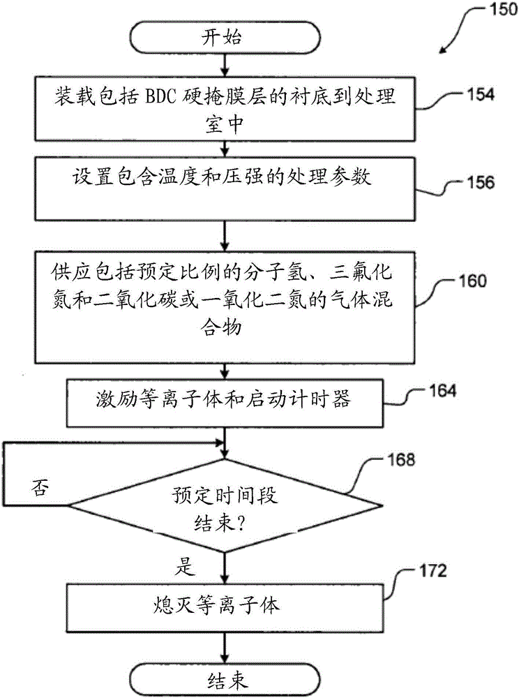
[0045] Substrate processing systems and methods according to the present disclosure are used to strip a boron doped carbon (BDC) hard mask layer from a substrate during substrate processing. The plasma is generated using a gas mixture that includes molecular hydrogen (H 2 ), nitrogen trifluoride (NF 3 ) and selected from carbon dioxide (CO 2 ) and nitrous oxide (N 2 The gases in the group consisting of O). The plasma treatment strips the BDC hard mask layer with high selectivity to the underlying film layer.

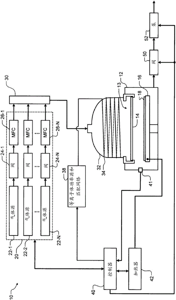
[0046] now refer to figure 1, an example of a substrate processing system 10 is shown. Although a specific processing chamber is shown, other types of chambers may also be used. The substrate processing system 10 includes a lower chamber 12 and a gas distribution device 13 such as a face plate or a showerhead 14 including spaced through holes. In some examples, substrate processing system 10 provides a remote or downstream plasma. A substrate support 16 may be ar...


PUM


Abstract

Systems and methods for processing a substrate include arranging a substrate including a film layer on a substrate support in a processing chamber. The film layer includes a boron doped carbon hard mask. A plasma gas mixture is supplied and includes molecular hydrogen, nitrogen trifluoride, and a gas selected from a group consisting of carbon dioxide and nitrous oxide. Plasma is struck in the processing chamber or supplied to the processing chamber for a predetermined stripping period. The plasma strips the film layer during the predetermined stripping period and the plasma is extinguished.

Description

[0001] Cross References to Related Applications [0002] This application claims the benefit of U.S. Provisional Application No. 62 / 186,029, filed June 29, 2015. The entire disclosure of the aforementioned referenced application is incorporated herein by reference. technical field [0003] The present invention relates to substrate processing systems and methods, and more particularly to systems and methods for stripping boron-doped carbon hardmask layers. Background technique [0004] The background description provided herein is for the purpose of generally presenting the context of the disclosure. The work of the presently named inventors (to the extent described in this Background section), and aspects of this specification that may not qualify as prior art at the time of filing, neither expressly nor implicitly admit that prior art for this disclosure. [0005] During processing of a substrate, such as a semiconductor wafer, one or more film layers are deposited on t...

Claims


Application Information

Patent Timeline
IPC IPC(8): H01L21/3065H01J37/32
CPCH01J37/32366H01L21/3065H01L21/31122H01L21/31144H01L21/32139H01L21/02129H01L21/02263H01L21/0257H01L21/67028H01J37/32082H01J37/3244
Inventor 戴维·T·马特森
Owner LAM RES CORP
Learn More