Cascade and deep coal-fired flue gas SO<3> removal system and method

A coal-fired flue gas removal technology, applied in separation methods, chemical instruments and methods, gas treatment, etc., to achieve the effect of inhibiting generation

Inactive Publication Date: 2017-01-18
ZHEJIANG UNIV
View PDF6 Cites 16 Cited by
  • Summary
  • Abstract
  • Description
  • Claims
  • Application Information

AI Technical Summary

Problems solved by technology

[0005] Among the existing coal-fired pollutant control equipment, there is no specific environmental protection equipment to control SO in flue gas. 3 With the increasingly stringent environmental protection requirements, it is

Method used


Image

  • Cascade and deep coal-fired flue gas SO&lt;3&gt; removal system and method
  • Cascade and deep coal-fired flue gas SO&lt;3&gt; removal system and method
  • Cascade and deep coal-fired flue gas SO&lt;3&gt; removal system and method

Examples


Embodiment 1

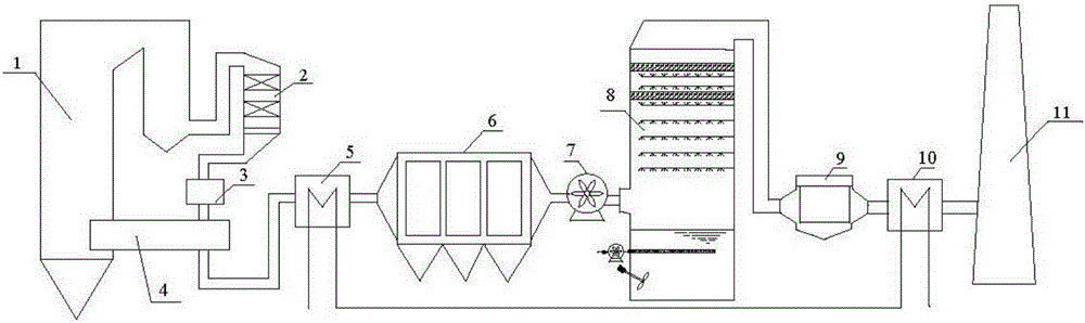
[0037] Reference figure 1 , A coal-fired flue gas SO 3 Cascade deep removal system, the system includes SCR denitrification device 2, alkaline absorbent injection device 3, air preheater 4, temperature adjustment and efficiency device, electrostatic precipitator 6, desulfurization tower 8 and wet electrostatic precipitator 9. The temperature enhancement device includes a cooling section 5 and a heating section 10, the SCR denitration device 2, the alkaline absorbent injection device 3, the air preheater 4, the temperature adjustment and efficiency device cooling section 5, the electrostatic precipitator 6, the desulfurization tower 8, and the wet electrostatic precipitator The heating section 10 of the temperature adjusting and synergizing device is arranged in sequence along the flue gas removal direction; a booster fan 7 is arranged between the electrostatic precipitator 6 and the desulfurization tower 8.

[0038] After the coal-fired flue gas comes out of the boiler 1, it passe...

Embodiment 2

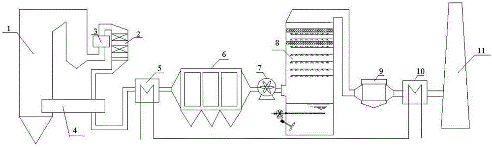
[0048] Reference figure 2 , A coal-fired flue gas SO 3 Step deep removal system, the system includes SCR denitrification device 2, alkaline absorbent injection device 3, air preheater 4, temperature adjustment and efficiency device, electrostatic precipitator 6, desulfurization tower 8 and wet electrostatic precipitator 9. The temperature enhancement device includes a cooling section 5 and a heating section 10, the SCR denitrification device 2, the air preheater 4, the temperature adjustment and efficiency device cooling section 5, the electrostatic precipitator 6, the desulfurization tower 8, the wet electrostatic precipitator 9, the temperature adjustment and efficiency device heating section 10 are arranged in sequence along the flue gas removal direction; the alkaline absorbent injection device 3 is arranged in front of the SCR denitrification device 2, and a booster fan 7 is provided between the electrostatic precipitator 6 and the desulfurization tower 8.

[0049] After the...

Embodiment 3

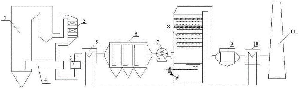
[0051] Reference image 3 , A coal-fired flue gas SO 3 Cascade deep removal system, the system includes SCR denitrification device 2, alkaline absorbent injection device 3, air preheater 4, temperature adjustment and efficiency device, electrostatic precipitator 6, desulfurization tower 8 and wet electrostatic precipitator 9. The temperature enhancement device includes a cooling section 5 and a heating section 10, the SCR denitrification device 2, the air preheater 4, the temperature adjustment and efficiency device cooling section 5, the electrostatic precipitator 6, the desulfurization tower 8, the wet electrostatic precipitator 9, the temperature adjustment and efficiency device heating section 10 are arranged in sequence along the flue gas removal direction; the position of the alkaline absorbent injection device 3 is set after the air preheater 4 and before the cooling section 5 of the temperature regulating and synergistic device. The electrostatic precipitator 6 and the d...


PUM

PropertyMeasurementUnit
Diameteraaaaaaaaaa

Abstract

The invention relates to a cascade and deep coal-fired flue gas SO<3> removal system and method. The system includes an SCR denitration device, an alkaline absorber spraying device, an air preheater, a temperature regulating and effect improving device, an electrostatic precipitator, a desulfurization tower and a wet electrostatic precipitator, wherein the temperature regulating and effect improving device comprises a cooling section and a heating section, the SCR denitration device, the air preheater, the cooling section of the temperature regulating and effect improving device, the electrostatic precipitator, the desulfurization tower and the wet electrostatic precipitator are sequentially arranged in the flue gas removal direction. The alkaline absorber spraying device is arranged in front of the SCR denitration device, behind the SCR denitration device, in front of the air preheater, behind the air preheater or in front of the cooling section of the temperature regulating and effect improving device. The cascade and deep coal-fired flue gas SO<3> removal system conducts cascade and deep removal on flue gas SO<3> through various pollutant control devices and achieves that the SO<3>emission concentration is less than 5 mg/Nm<3>.

Description

Technical field [0001] The invention belongs to the technical field of coal-fired flue gas pollutant removal, and specifically relates to a coal-fired flue gas SO 3 Step depth removal system and method. Background technique [0002] Coal-fired thermal power generation is currently the main form of electricity production in my country. my country’s thermal power generation is as high as 80% of the total power generation, of which coal-fired electricity installed capacity accounts for 75% of the total capacity. In 2014, my country's total energy consumption was 3.61 billion tons of standard coal, and coal consumption accounted for 66% of total energy consumption. China's coal-based energy supply pattern will not change in the future. [0003] In coal-fired power plants, SO 3 There are two main sources of sulphur: One is in the combustion process, the combustible sulfur contained in coal burns to generate SO 2 After part of SO 2 Is further oxidized to form SO 3 ; Second, in the selec...

Claims


Application Information

Patent Timeline
IPC IPC(8): B01D53/86B01D53/50B01D53/79B01D53/75B01D53/18B03C3/014
CPCB01D53/18B01D53/75B01D53/79B01D53/8609B03C3/014B01D2251/60B01D2258/0283
Inventor 高翔郑成航骆仲泱倪明江岑可法王丁振张涌新翁卫国王毅吴卫红周劲松方梦祥程乐鸣王勤辉王树荣
Owner ZHEJIANG UNIV
Why Eureka
Try Eureka