Turbine blade molding line
A technology for steam turbine blades and molding lines, which is applied to furnace types, mechanical equipment, engine components, etc. It can solve the problems of high energy consumption and low processing efficiency, and achieve the effect of improving work efficiency and reducing labor
- Summary
- Abstract
- Description
- Claims
- Application Information
AI Technical Summary
Problems solved by technology
Method used
Image
Examples
Embodiment 1
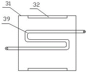
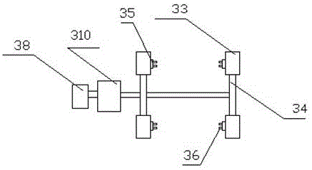
[0044] This embodiment includes a blank warehouse 1, a conveyor, a heating furnace 3, a blank forging machine 5, a blade forming machine 7, a demoulding machine 9 and an edge trimming machine 11; there are four conveyors, which are respectively the first conveyor 2 , the second conveyor 6, the third conveyor 8 and the fourth conveyor 10, the first conveyor 2 is installed between the blank warehouse 1 and the heating furnace 3, the second conveyor 6 is installed between the blank forging machine 5 and the blade forming Between the machine 7, the third conveyor 8 is installed between the blade forming machine 7 and the demoulding machine 9, and the fourth conveyor 10 is installed between the demoulding machine and the 9 edge trimmer 11; the heating furnace 3 and the blank A conveyor ramp 4 is installed between the forging machines 5. The first conveyor 2 transports the blanks in the blank storehouse 1 to the feed port of the heating furnace 3. After being heated, it is sent out f...
Embodiment 2
[0046] This embodiment includes a blank warehouse 1, a conveyor, a heating furnace 3, a blank forging machine 5, a blade forming machine 7, a demoulding machine 9 and an edge trimming machine 11; there are four conveyors, which are respectively the first conveyor 2 , the second conveyor 6, the third conveyor 8 and the fourth conveyor 10, the first conveyor 2 is installed between the blank warehouse 1 and the heating furnace 3, the second conveyor 6 is installed between the blank forging machine 5 and the blade forming Between the machine 7, the third conveyor 8 is installed between the blade forming machine 7 and the demoulding machine 9, and the fourth conveyor 10 is installed between the demoulding machine and the 9 edge trimmer 11; the heating furnace 3 and the blank A conveyor ramp 4 is installed between the forging machines 5. The first conveyor 2 transports the blanks in the blank storehouse 1 to the feed port of the heating furnace 3. After being heated, it is sent out f...
Embodiment 3
[0051] This embodiment includes a blank warehouse 1, a conveyor, a heating furnace 3, a blank forging machine 5, a blade forming machine 7, a demoulding machine 9 and an edge trimming machine 11; there are four conveyors, which are respectively the first conveyor 2 , the second conveyor 6, the third conveyor 8 and the fourth conveyor 10, the first conveyor 2 is installed between the blank warehouse 1 and the heating furnace 3, the second conveyor 6 is installed between the blank forging machine 5 and the blade forming Between the machine 7, the third conveyor 8 is installed between the blade forming machine 7 and the demoulding machine 9, and the fourth conveyor 10 is installed between the demoulding machine and the 9 edge trimmer 11; the heating furnace 3 and the blank A conveyor ramp 4 is installed between the forging machines 5. The first conveyor 2 transports the blanks in the blank storehouse 1 to the feed port of the heating furnace 3. After being heated, it is sent out f...
PUM
 Abstract
Description
Claims
Application Information
 - R&D
- Intellectual Property
- Life Sciences
- Materials
- Tech Scout
- Unparalleled Data Quality
- Higher Quality Content
- 60% Fewer Hallucinations
Browse by: Latest US Patents, China's latest patents, Technical Efficacy Thesaurus, Application Domain, Technology Topic, Popular Technical Reports.
© 2025 PatSnap. All rights reserved.Legal|Privacy policy|Modern Slavery Act Transparency Statement|Sitemap|About US| Contact US: help@patsnap.com


