Plastic pipe extrusion equipment heat-exchange circulatory system and application method thereof

A technology of extrusion equipment and plastic pipes, which is applied in the field of heat exchange circulation system of plastic pipe extrusion equipment, can solve the problems of insufficient drying of extruded materials, waste of power resources and energy, and quality problems, so as to avoid heat loss and save energy. Energy and the effect of improving the utilization rate

Active Publication Date: 2017-01-18
ZHEJIANG SHUANGLIN PLASTIC MACHINERY
View PDF6 Cites 4 Cited by
  • Summary
  • Abstract
  • Description
  • Claims
  • Application Information

AI Technical Summary

Problems solved by technology

The traditional hot air dryer needs a lot of heat energy consumption, consumes and wastes a lot of power resources and energy; the thermal efficiency is low, and the extruded material cannot be fully dried during the high-efficiency extrusion process, and it is easy to retain residual moisture in the material that has not been fully dried, so It is easy to cause quality problems to the product

Method used


Image

  • Plastic pipe extrusion equipment heat-exchange circulatory system and application method thereof
  • Plastic pipe extrusion equipment heat-exchange circulatory system and application method thereof

Examples


Embodiment 1

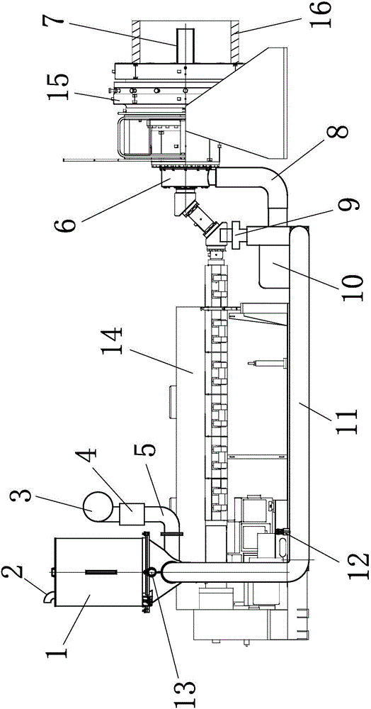
[0018] Embodiment 1: as figure 1 As shown, a heat exchange circulation system of plastic pipe extrusion equipment includes a single-screw plastic extruder 14 and a plastic extrusion die body 15, and the input end of the single-screw plastic extruder is connected with a dryer barrel 1 to dry An auxiliary heating cylinder 5 and an auxiliary fan 3 are connected to the barrel of the machine, a suction fan 10 is arranged at the mold body of the plastic extrusion mold, and a heat exchange suction pipe 7 is arranged at the axis of the mold body of the plastic extrusion mold. Trachea links to each other with suction blower by front suction pipe 8, and the output end of suction blower communicates with dryer barrel through hot blast air delivery pipe 11. A heat exchange gas collection box 6 is arranged between the heat exchange suction pipe and the front suction pipe. The suction fan place is provided with a noise reduction device 9 . A pressure relief valve 12 is arranged on the hot...

Embodiment 2

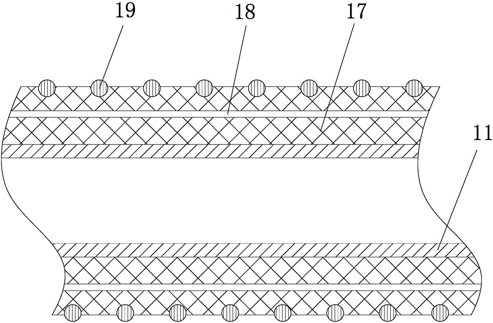
[0021] Embodiment 2: The structure of this embodiment is basically the same as that of Embodiment 1, the difference is that, as figure 2 As shown, the outer side of the hot air supply pipe is provided with a thermal insulation cotton cover 17, and the inside of the thermal insulation cotton cover is provided with several elastic positioning lines 18. The elastic positioning lines are parallel to the axial direction of the hot air supply pipe, and several elastic positioning lines are distributed around the axis of the thermal insulation cotton cover. An elastic backguy 19 is arranged on the outer side of the thermal insulation cotton cover, and the elastic backguy is helical and embedded in the outer surface of the thermal insulation cotton cover. The thermal insulation cotton cover is wrapped on the outside of the hot air supply pipe, and the thermal insulation cotton cover can keep the hot air supply pipe warm, and can prevent the condensation water on the surface of the hot...


PUM


Abstract

The invention relates to plastic pipe production equipment, especially to a plastic pipe extrusion equipment heat-exchange circulatory system and an application method thereof. The plastic pipe extrusion equipment heat-exchange circulatory system comprises a single-screw plastic extruder and a plastic extrusion mold body. An input end of the single-screw plastic extruder is connected to a drying machine charging barrel. An auxiliary heating cylinder and an auxiliary blower fan are connected on the drying machine charging barrel. A suction fan is arranged at the plastic extrusion mold body. A heat-exchange air-suction pipe is arranged at the axis of the plastic extrusion mold body. The heat-exchange air-suction pipe is connected to the suction fan through a front air-suction pipe. An output end of the suction fan is communicated with the drying machine charging barrel through a hot air induction-pipe, which is provided with a thermal insulation device for thermal insulation of the hot air induction-pipe. According to the system, residual heat during extrusion of plastic can be recovered and utilized, energy consumption during drying of plastic can be reduced, and utilization rate of heat can be raised.

Description

technical field [0001] The invention relates to a plastic pipe production equipment, in particular to a plastic pipe extrusion equipment heat exchange cycle system and its application method. Background technique [0002] In the extrusion process of plastic products, the raw materials are generally dried. The traditional material drying method is to use a hot air dryer to dry the material to remove the moisture in the raw material. The traditional hot air dryer uses a cut-in hot air drying method to dry the material. The hot air of the type dryer adopts electric heating to carry out circulating hot air drying on the desiccant silo. Because the source of hot air for this type of dryer is the heating cylinder and fan in its own structure, the purpose of drying is achieved through system control according to the drying temperature of the material. Because the drying principle and mechanism of this type of dryer require a lot of heating power and consume a lot of energy in the ...

Claims


Application Information

Patent Timeline
Patent Type & Authority Applications(China)
IPC IPC(8): B29C47/08B29C47/78B29B13/06B29L23/00
CPCB29B13/06B29C48/276B29C48/793B29L2023/22Y02P70/10
Inventor 孔岱东党辉张梦芳
Owner ZHEJIANG SHUANGLIN PLASTIC MACHINERY
Why Eureka
Try Eureka