A helium-neon gas frequency-sweeping laser
A laser and gas technology, applied in the laser field, can solve the problems of increasing the distance between the two mirrors, reducing the output power of the laser, and not emitting light, so as to ensure the position accuracy, improve the environmental adaptability, and reduce the discharge current.
Inactive Publication Date: 2011-09-14
FLIGHT AUTOMATIC CONTROL RES INST
View PDF0 Cites 0 Cited by
- Summary
- Abstract
- Description
- Claims
- Application Information
AI Technical Summary
Problems solved by technology
1. Existing laser tubes are made of ordinary glass materials such as quartz. The helium gas permeability is high and can only be used at room temperature. The environmental requirements are high and the service life of the laser is short.
2. The laser adopts a single anode and single cathode structure, and the discharge gain area is small. In order to increase the gain, the discharge distance between the electrodes can only be extended, which will increase the distance between the two mirrors and cause difficulties in the installation and adjustment of the laser.
3. The discharge tube 6 is a cantilever structure, which is prone to deformation and changes relative to the position of the reflector, which will cause the laser to output light weakly or even not emit light
4. The shell 3 is a thin-walled part, which is easy to deform, and it is difficult to ensure the parallelism between the two mirrors, and the survival rate is low
5. The piezoelectric ceramic component is installed inside the laser tube. Once the component fails, there is no rescue measure, which can only cause the entire laser to be scrapped
6. This type of laser outputs natural light. When it is necessary to obtain polarized light, it is necessary to install a reflector at the outer end of the laser to form a Brewster angle. The optical path is complicated, which reduces the output power of the laser.
Method used
View moreImage
Smart ImageViewing Examples

Examples
Embodiment Construction
Login to view more PUM
 Abstract
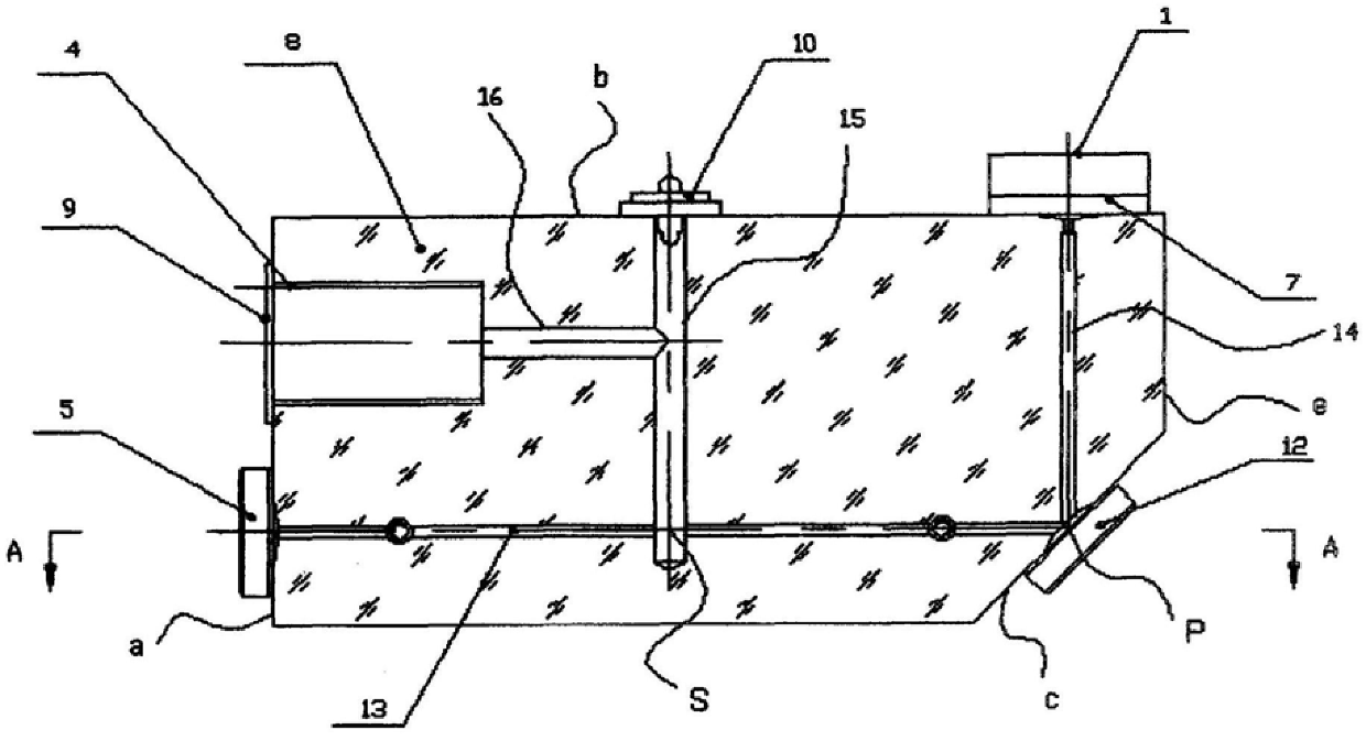
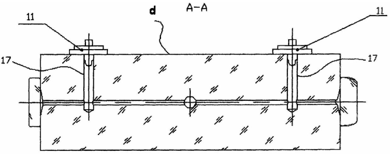
The invention belongs to the laser technology and relates to the improvement of a helium-neon gas frequency-sweeping laser. It consists of a piezoelectric ceramic component [1] with a micro-displacement mirror [7], a cathode [4], an output mirror [5], and a helium-neon gas that fills the laser cavity. It is characterized in that there is a body [8] made of glass ceramics, there is a through-through first capillary hole [13] from the left end surface a to the chamfered surface c, and there is a first capillary hole [13] from the chamfered surface c to the upper surface b The through second capillary hole [14] has a vertical non-gain discharge hole [15] perpendicular to the first capillary hole [13] on the upper surface b, and a vertical non-gain discharge hole [15] in the center of the inner end surface of the cathode mounting cavity. The non-gain discharge hole [15] vertically passes through the horizontal non-gain discharge hole [16], and there are two electrode holes [17] vertically connected with the first capillary hole [13] on the side d. The invention can be used in harsh environments, has long service life, small volume, high reliability, easy maintenance and easy access to polarized light.
Description
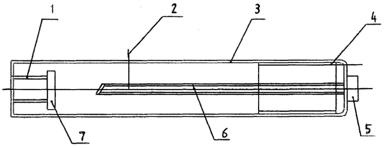
A helium-neon gas frequency-sweeping laser technical field The invention belongs to the laser technology and relates to the improvement of a helium-neon gas frequency-sweeping laser. Background technique Referring to Fig. 1 for the structure of the existing frequency-sweeping laser, it is composed of a discharge tube 6 and an optical resonant cavity. The center of the laser is a capillary glass discharge tube 6, and the shell 3 is a gas storage part. Two ends of the shell 3 are pasted The reflectors 5 and 7, which are perpendicular to the discharge capillary and parallel to each other, form a flat-concave resonant cavity. Both reflectors are coated with multi-layer dielectric films. The reflector 7 is a total reflection mirror, and the reflector 5 is a semi-transparent and semi-reflective output. Reflector. The discharge tube 6 is filled with a certain pressure and proportion of helium-neon mixed gas as a working substance. A discharge circuit is formed by a single catho...
Claims
Login to view more Application Information
Patent Timeline
 Patent Type & Authority Patents(China)
IPC IPC(8): H01S3/223H01S3/03
Inventor 刘元正韩宗虎
Owner FLIGHT AUTOMATIC CONTROL RES INST
- R&D Engineer
- R&D Manager
- IP Professional
Why Eureka
- Industry Leading Data Capabilities
- Powerful AI technology
- Patent DNA Extraction
Try Eureka
Browse by: Latest US Patents, China's latest patents, Technical Efficacy Thesaurus, Application Domain, Technology Topic.
© 2024 PatSnap. All rights reserved.Legal|Privacy policy|Modern Slavery Act Transparency Statement|Sitemap