

Anti-blocking method and equipment for biomass boiler worm feeder
A technology of screw feeder and biomass boiler, which is applied in the direction of conveyor control device, combustion method, supply configuration, etc., and can solve problems such as setting too high motor over-torque protection setting, manual cleaning, and insufficient fuel quality , to achieve the effect of reducing the probability of material blockage, resisting the decline of fire-fighting and tempering ability, and ensuring continuous and stable operation
- Summary
- Abstract
- Description
- Claims
- Application Information
AI Technical Summary
Problems solved by technology
Method used
Image

Examples
Embodiment 1
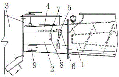
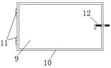
[0036] It can be seen from the accompanying drawings that the present invention relates to an anti-blocking device for a biomass boiler screw feeder, comprising a biomass boiler screw feeder 1 and a plug tube 2, the inlet of the plug tube 2 is connected to the screw feeder of the biomass boiler The outlet of the feeder 1 and the outlet of the plug tube 2 are connected to the inlet of the feed tank 3; according to the main cause of the feeder blocking, the length of the plug tube is shortened, and the screw push rod of the screw feeder is extended. The improvement measures of the length, and opening holes on the side of the plug tube to reduce the difficulty of cleaning the plug, and at the same time, in order to avoid the reduction of the anti-tempering function of the plug, the measures of anti-tempering baffle plus assembly weight and limit block are adopted ,details as follows:
[0037] The plug tube 2 is a shortened plug tube, the length of the screw push rod of the screw ...
Embodiment 2
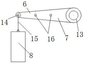
[0044] The basic principle of the second embodiment is the same as that of the first embodiment, but the structure is different. It is a kind of anti-blocking device for the screw feeder of the biomass boiler, including the screw feeder of the biomass boiler and the plug pipe, and the inlet of the plug pipe It is connected to the outlet of the screw feeder of the biomass boiler, and the outlet of the plug pipe is connected to the inlet of the feeding trough; its characteristic is that the plug pipe is a shortened type plug pipe, and a rotatable screw is installed in the plug pipe The anti-temper baffle, the rotating shaft of the anti-temper baffle stretches out to the plug tube, and the rotating shaft extending out of the plug tube is connected with a rotating mechanism that controls the rotation of the anti-temper baffle.
[0045] The rotating mechanism is a solenoid valve or an electric rotating mechanism, and a solenoid valve or an electric control device is connected to the...
PUM
| Property | Measurement | Unit |
|---|---|---|
| Length | aaaaa | aaaaa |
Abstract
Description
Claims
Application Information