Casting technique of supporting frame for building

A technology of casting technology and support frame, which is applied in the direction of manufacturing tools, casting molding equipment, casting molds, etc., can solve the problems of sand erosion, sintering, and sand sticking on the surface of castings, so as to improve the quality of castings, improve the feeding effect, reduce the The effect of sticky sand

Inactive Publication Date: 2017-02-01
KOCEL STEEL
View PDF6 Cites 14 Cited by
  • Summary
  • Abstract
  • Description
  • Claims
  • Application Information

AI Technical Summary

Problems solved by technology

There is a 110mm wide groove on the back of the bottom flange of the casting, which is easy to stick sand
There is a small hole with a diameter of about 130mm in the middle of the top of the casting, which is not conducive to the positioning and fixing of the sand core
Due to the narrow space in the inner cavity of the casting, sand erosion and sintering are prone to occur during the actual pouring of molten steel and filling the mold, resulting in the problem of sand sticking on the surface of the casting

Method used


Image

  • Casting technique of supporting frame for building
  • Casting technique of supporting frame for building
  • Casting technique of supporting frame for building

Examples


Embodiment Construction

[0016] The casting process of the building support frame of the present invention will be described in detail below in conjunction with the accompanying drawings.

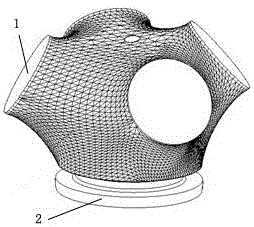
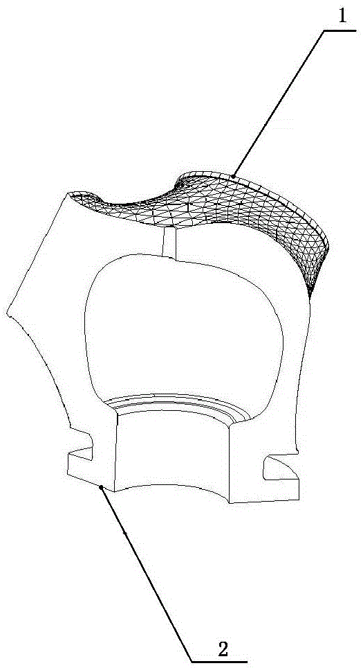
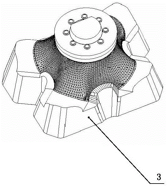
[0017] Such as Figure 3 to Figure 7 As shown, the casting process of the building support frame of the present invention includes the following processes: the production of a real pattern and the production of a sand core: the cavity of the casting is formed by combining the real sample molding of the outer cavity with the sand core of the inner cavity, and the real sample of the outer cavity includes the casting Pattern and the supporting tire plate 3 that is integrally covered on the upper side of the supporting end of the casting pattern, and the top plane of the supporting tire plate 3 is used as the modeling parting surface 4, such as image 3 and Figure 4 shown. In order to ensure the size of the casting and the later mechanical processing needs, during the design process of the real pattern, when determi...


PUM

PropertyMeasurementUnit
thicknessaaaaaaaaaa

Abstract

The invention relates to the technical field of casting, in particular to a casting technique of a supporting frame for building. The casting technique comprises the following processes that an outer cavity real sample model is adopted to be combined with an inner cavity sand core to form a cavity of a casting; the outer cavity real sample comprises a casting model sample and a supporting bed mould wholly covering the upper side of the supporting end of the casting model sample, and the top plane of the supporting bed mould serves as a model parting surface; the inner cavity sand core comprises a first sand core body for forming an inner cavity and a second sand core body for forming a small top hole, the second sand core body is inserted into the first sand core in a matched manner, and the bottom of the first sand core extends to the lower side of a flange hole and is fixed to a lower sand mould through an arbor; an open riser is arranged at the supporting end of the casting, a riser neck is arranged between the open riser and the end face of the supporting end, and a blind riser is arranged in the flange hole of the casting; the inner cavity of the casting, the normal direction of the end face of the flange end and the periphery of the flange end are each provided with a direct cooling chiller; and an open type gating system is adopted, a flow gate of an ingate is located below the blind riser of the inner cavity and is directly communicated with the blind riser, and a filter is arranged at the tail end of the flow gate.

Description

technical field [0001] The invention relates to the technical field of casting, in particular to a casting process of a building support frame. Background technique [0002] Such as figure 1 Shown is a casting of a support frame for construction. The structure of the casting includes an irregular curved surface structure, including four support ends 1 and a flange end 2 at the bottom. The wall thickness of the casting is relatively large, and the inner cavity space is narrow. The thickness is not uniform, and the quality of the outer surface is high. There is a 110mm wide groove on the back of the bottom flange of the casting, which is easy to stick sand. There is a small hole with a diameter of about 130mm in the middle of the top of the casting, which is not conducive to the positioning and fixing of the sand core. Due to the narrow space in the inner cavity of the casting, sand erosion and sintering are prone to occur during the actual pouring of molten steel and filli...

Claims


Application Information

Patent Timeline
Patent Type & Authority Applications(China)
IPC IPC(8): B22C9/02B22C7/00B22C9/08B22C9/10B22C9/24
CPCB22C9/02B22C7/00B22C9/082B22C9/086B22C9/088B22C9/103B22C9/106B22C9/24
Inventor 苏志东
Owner KOCEL STEEL
Why Eureka
Try Eureka