Biogas pressurizing water-washing device

A technology of pressurized water washing and biogas, which is applied in the direction of gas fuel, petroleum industry, and separation of dispersed particles. It can solve the problems of not providing supporting equipment, high manufacturing cost, and complicated equipment, and achieve improved water washing effect, good uniformity, and The effect of large contact area

Inactive Publication Date: 2017-02-15
CHANGSHU NO 2 CHEM ENG EQUIP PLANT +1
View PDF8 Cites 0 Cited by
  • Summary
  • Abstract
  • Description
  • Claims
  • Application Information

AI Technical Summary

Problems solved by technology

The devices involved in these patents are not limited to examples, which are relatively complicated and costly to manufacture.
[0004] CN203777898U discloses "absorption tower for biogas pressurized water washing method purification" has the advantages of simple structure and low manufacturing cost and can objectively fulfill the technical effect recorded in paragraph 0013 of the description, but the patent scheme does not give a separate and Enlightenment of water inlet pipe, water outlet pipe, air inlet pipe, air outlet pipe and other related supporting devices, but these supporting devices are indispensable for the formation of biogas impurity removal and purification equipment, and even related to the purification efficiency, purification effect and safety of purification operations important factor

Method used


Image

  • Biogas pressurizing water-washing device

Examples


Embodiment Construction

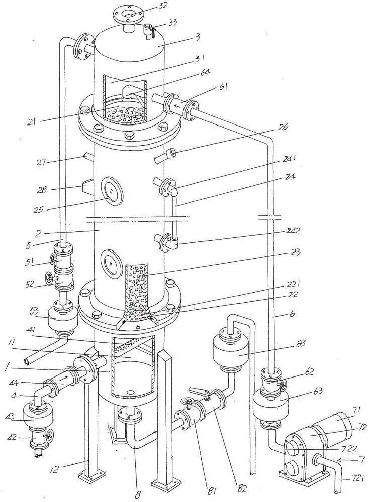
[0017] See figure 1 , shows an air intake tank 1, which is supported on the floor of the place of use in the use state; shows an absorption tower 2, which is fixed to the upper part of the aforementioned air intake tank 1 and The bottom of the absorption tower chamber 21 of the absorption tower 2 is fixed with a packing supporting plate 22, and a through hole 221 is opened in a dense state on the packing supporting plate 22, and the through hole 221 communicates with the air inlet tank cavity 11 of the air inlet tank 1 , packing 23 is arranged in absorption tower cavity 21, and this packing 23 is supported by packing supporting plate 22, and the tower body of absorption tower 2 is provided with liquid level gauge 24, and this liquid level gauge 24 communicates with absorption tower cavity 21; Shown a tower cap 3, this tower cap 3 is fixed with the top of absorption tower 2 and is provided with a safety valve interface 32 that communicates with the tower cap chamber 31 of tower...


PUM


Abstract

A biogas pressurizing water-washing device comprises a gas incoming tank, an absorbing tower, a tower cap, a gas incoming pipe, a gas outgoing pipe, a water incoming pipe and a water outgoing pipe. The absorbing tower is fixed to the upper portion of the gas incoming tank, a filler supporting plate is arranged at the bottom of the absorbing tower, a through hole is formed in the filler supporting plate, a filler is arranged in an absorbing tower cavity, a liquid level meter is arranged on a tower body, the tower cap is fixed to the absorbing tower, a safety valve port is arranged at the top of the tower cap, one end of the gas incoming pipe goes into a gas incoming tank cavity while the other end of the same is connected with a gas supply device, and a pressure stabilizing valve, a gas flow meter and a gas incoming pipe one-way control valve are arranged in the middle of the gas incoming pipe; one end of the gas outgoing pipe is connected with the upper side portion of the tower cap while the other end of the same is connected with a gas storing device, a gas outgoing pipe depressurizing valve, a gas outgoing pipe ball valve and a gas outgoing pipe flow meter are arranged in the middle of the gas outgoing pipe, one end of the water incoming pipe is connected with the lower side face of the tower cap while the other end of the same is connected with a water supply mechanism which is matched with a water collection tank, one end of the water outgoing pipe is connected with the bottom of the gas incoming tank while the other end of the same extends into the water collection tank, and the filler is a ceramic step ring. By the biogas pressurizing water-washing device, water-washing efficiency and effect are improved, and completeness, safety and operability of the whole system are embodied.

Description

technical field [0001] The invention belongs to the technical field of biogas impurity removal and purification equipment, and in particular relates to a biogas pressurized water washing device. Background technique [0002] Biogas is a low-calorific-value biomass gas mainly composed of methane and carbon dioxide. It can be refined into gas that meets the standards of bio-natural gas through purification processes such as desulfurization, decarbonation, and dehydration. Biogas purification generally has the following methods: absorption method, pressure swing adsorption method, low temperature condensation method and membrane separation method. Water washing belongs to the category of absorption method. Compared with other methods mentioned above, absorption method has simple process, low equipment cost and high treatment efficiency Strengths, so it is valued by the industry. [0003] The technical information about biogas impurity removal and purification equipment can be ...

Claims


Application Information

Patent Timeline
Patent Type & Authority Applications(China)
IPC IPC(8): B01D53/18C10L3/10
CPCB01D53/18C10L3/101
Inventor 陈启东姜敏泉谢瑞祥
Owner CHANGSHU NO 2 CHEM ENG EQUIP PLANT
Why Eureka
Try Eureka