Internal supporting positioning device for girth welding of flange plates of carrier rocket tanks

A technology of girth welding and launch vehicle, which is applied in the direction of auxiliary devices, welding equipment, auxiliary welding equipment, etc., can solve the difficulty of flange transition joint girth welding, residual stress storage tank quality and reliability hidden dangers, assembly quality Require high-level issues to achieve the effect of improving labor productivity and safety production level, reducing workers' work environment pollution, and improving welding quality

Active Publication Date: 2017-02-15
CAPITAL AEROSPACE MACHINERY +1
View PDF7 Cites 11 Cited by
  • Summary
  • Abstract
  • Description
  • Claims
  • Application Information

AI Technical Summary

Problems solved by technology

[0004] The welding difficulty of this transition joint lies in that the welding zone is thin, and the thickness of the welding zone is 5mm; the weld seam is a circular weld seam, which requires the two workpieces to be welded to have a high coaxiality after assembly; the rigidity is poor, and the ability to resist deformation is poor, and the assembly quality The requirements are high; the above situation greatly increases the difficulty of welding the ring seam of the flange transition joint, and relevant measures need to be taken to solve it
[0005] For many years, the fusion welding method has been mostly used in the welding of the tank bottom flange in our country. Since the structural material of the bottom of the tank belongs to high-strength aluminum alloy, the fusion welding method will bring many adverse effects, such as the low strength coefficient of the joint. Large thickness compensation on the surface reduces the load ratio of the storage tank virtually; welding defects and large residual stress and deformation often cause hidden dangers to the quality and reliability of the storage tank, etc.
[0006] At present, there is no technical equipment in China that can use friction stir welding for the annular seam of the transition joint of the tank bottom flange to play the role of internal support positioning and pressing. The gap can meet the requirements of friction stir welding

Method used


Image

  • Internal supporting positioning device for girth welding of flange plates of carrier rocket tanks
  • Internal supporting positioning device for girth welding of flange plates of carrier rocket tanks
  • Internal supporting positioning device for girth welding of flange plates of carrier rocket tanks

Examples


Embodiment Construction

[0026] Below in conjunction with accompanying drawing and specific embodiment the present invention is described in further detail:

[0027] This device is to ensure that when friction stir welding is used for the circular seam of the transition joint of the flange plate at the bottom of the carrier rocket storage tank, the assembly gap and the stagger amount are all less than 0.2mm, and the near gapless assembly can be realized.

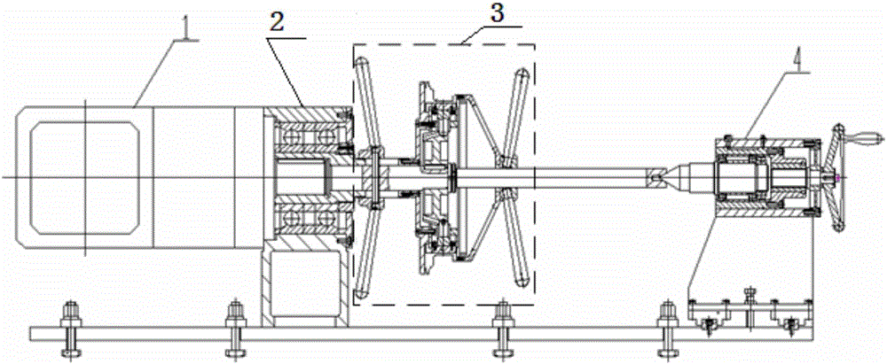
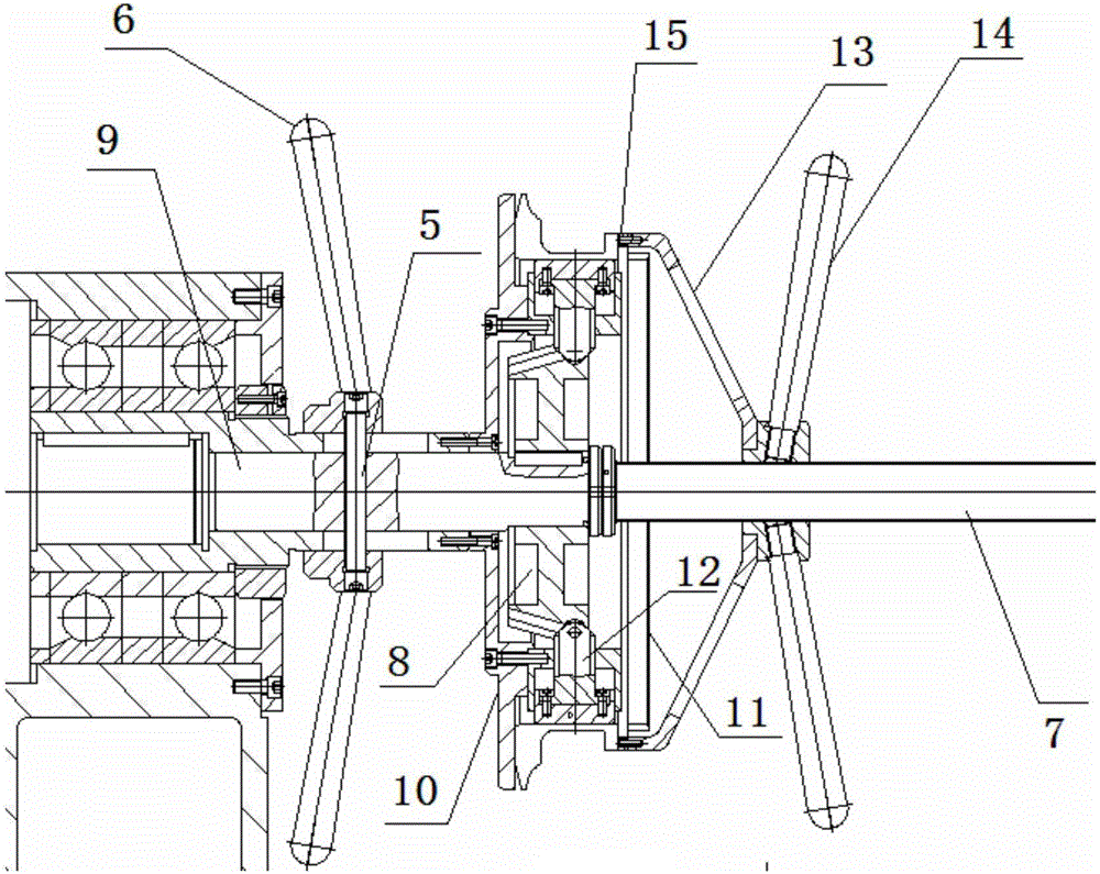
[0028] like figure 1 Shown is a functional diagram of the friction stir welding positioning device for the flange transition joint of the storage tank. It can be seen from the figure that an inner support positioning device for welding the flange of the launch vehicle tank flange includes a power mechanism 1, Circumferential overall rotation mechanism 2, radial tension mechanism 3 and axial compression mechanism 4; wherein, one end of the power mechanism 1 is fixedly installed on the input end of the external planetary reducer along the shaft, and t...


PUM


Abstract

The invention relates to the field of processing technology equipment for aerospace products, in particular to an internal supporting positioning device for girth welding of flange plates of carrier rocket tanks. The internal supporting positioning device comprises a power mechanism, a circumferential overall rotating mechanism, a radial supporting-tightening mechanism and an axial pressing mechanism. One end of the circumferential overall rotating mechanism is coaxially and fixedly installed at one end of the power mechanism. The radial supporting-tightening mechanism is coaxially and fixedly installed at the other end of the circumferential overall rotating mechanism. The axial pressing mechanism is coaxially and fixedly installed at the other end of the radial supporting-tightening mechanism. External workpieces are fixed between the radial supporting-tightening mechanism and the axial pressing mechanism in the axial direction. The power mechanism drives the circumferential overall rotating mechanism to achieve rotating movement of the workpieces in the axis directions of the workpieces. The device can internally support and tighten the two welded workpieces simultaneously, coaxiality adjustment is completed while supporting and tightening are conducted, the welded workpieces can be clamped in the axial direction, and the device needs to have enough structural rigidity so that welding deformation of products can be borne and reduced.

Description

technical field [0001] The invention relates to the field of aerospace product processing technology equipment, in particular to an inner support positioning device used for welding the circular seam of a flange plate of a carrier rocket storage tank. Background technique [0002] The propellant tank is the fuel tank of the launch vehicle, which has a large diameter, thin material and weak structural rigidity. The storage tank is generally welded by structural parts such as front and rear short shells, front and rear bottoms, and middle shell sections. The front and rear bottoms usually include a transition joint welding structure with flanges, and the product structure material is aluminum alloy. [0003] Product welding adopts advanced welding methods such as friction stir welding, which require the product axis to be placed horizontally and the product to rotate along the axis. [0004] The welding difficulty of this transition joint lies in that the welding zone is thi...

Claims


Application Information

Patent Timeline
Patent Type & Authority Applications(China)
IPC IPC(8): B23K37/053
CPCB23K37/053
Inventor 高彦军郝云飞马建波杜宪策李迎孟令博王忠义李占辉孔德跃
Owner CAPITAL AEROSPACE MACHINERY
Why Eureka
Try Eureka