Spectrophotometer
A spectrophotometer and laser technology, applied in the field of photometer, to achieve ultra-high measurement accuracy and repeatability accuracy, improve noise anti-interference ability, and expand the application field and scope of application
- Summary
- Abstract
- Description
- Claims
- Application Information
AI Technical Summary
Problems solved by technology
Method used
Image
Examples
Embodiment 1
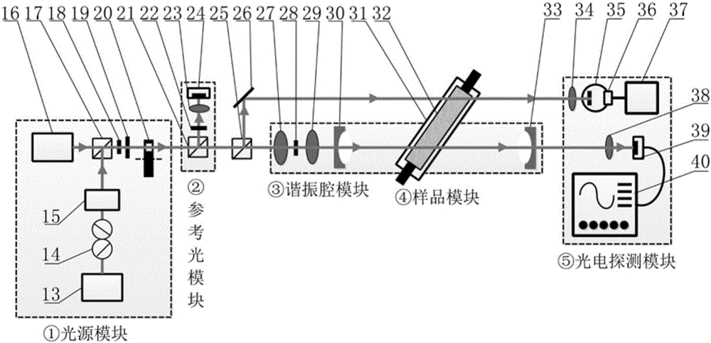
[0050] figure 2 It is a schematic diagram of the optical path when the spectrophotometer of the present invention measures the transmission element. It can be seen from the figure that the spectrophotometer of the present invention includes a light source module, a reference light module, a photoelectric detection module, a resonant cavity module and a sample module:
[0051] The light source module includes a tunable laser 13 and a pulsed laser 16. In the laser output direction of the tunable laser 13, a laser power adjustment device 14, a monochromator 15, a first beam splitter 17, an aperture 18, and a polarizer are sequentially arranged. 19 and a chopper 20, the laser output direction of the pulsed laser 16 is the first beam splitter 17, the diaphragm 18, the polarizer 19 and the chopper 20;
[0052] The reference light module includes a second beam splitter 21, and the second beam splitter 21 is arranged on the output optical path of the light source module. The second b...
Embodiment 2
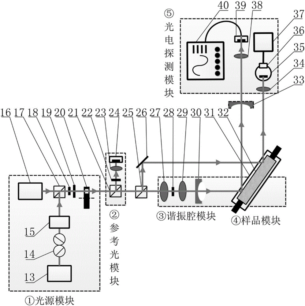
[0058] image 3 It is a schematic diagram of the optical path when the spectrophotometer of the present invention measures reflective elements. As can be seen from the figure, the spectrophotometer of the present invention includes a light source module, a reference light module, a photoelectric detection module, a resonant cavity module and a sample module:
[0059] The light source module includes a tunable laser 13 and a pulsed laser 16. In the laser output direction of the tunable laser 13, a laser power adjustment device 14, a monochromator 15, a first beam splitter 17, an aperture 18, and a polarizer are sequentially arranged. 19 and a chopper 20, the laser output direction of the pulsed laser 16 is the first beam splitter 17, the diaphragm 18, the polarizer 19 and the chopper 20;
[0060] The reference light module includes a second beam splitter 21, and the second beam splitter 21 is arranged on the output optical path of the light source module. The second beam split...
PUM
| Property | Measurement | Unit |
|---|---|---|
| refractive index | aaaaa | aaaaa |
Abstract
Description
Claims
Application Information
 - R&D
- Intellectual Property
- Life Sciences
- Materials
- Tech Scout
- Unparalleled Data Quality
- Higher Quality Content
- 60% Fewer Hallucinations
Browse by: Latest US Patents, China's latest patents, Technical Efficacy Thesaurus, Application Domain, Technology Topic, Popular Technical Reports.
© 2025 PatSnap. All rights reserved.Legal|Privacy policy|Modern Slavery Act Transparency Statement|Sitemap|About US| Contact US: help@patsnap.com


