
System for realizing automatic-balancing sensing and control of water level of lysimeter

A technology of automatic balance and lysimeter, applied in control/adjustment system, liquid level control, non-electric variable control, etc., can solve the problems of high construction and maintenance costs, heavy workload, manual observation of water level and operation, etc., to achieve Ensure normal growth, prevent waterlogging and drought, and reduce manual operations

Inactive Publication Date: 2017-02-15
HOHAI UNIV
View PDF4 Cites 3 Cited by
  • Summary
  • Abstract
  • Description
  • Claims
  • Application Information

AI Technical Summary

Problems solved by technology

Domestically, Liu Shiping was the first to design the method of moving the Martens jar up and down along the vertical guide rail to keep the internal and external water levels equal. However, manual observation of the water level and operation are still required. The workload is heavy, the equipment is complicated, and the investment is also high.
[0003] At present, when using lysimeters for research, the method of setting a fixed internal water level for a specific period of time is often used. The technology is also mature, but this does not match the reality of frequent changes in groundwater levels caused by rainfall and drainage in the southern region
It is technically feasible to measure and compare the internal and external water levels by using a water level sensor, and automatically control it through a microcomputer, but the construction and maintenance costs are high, and there are not many practical applications in China.

Method used


Image

  • System for realizing automatic-balancing sensing and control of water level of lysimeter
  • System for realizing automatic-balancing sensing and control of water level of lysimeter
  • System for realizing automatic-balancing sensing and control of water level of lysimeter

Examples


Embodiment Construction

[0017] The present invention will be further described below in conjunction with the accompanying drawings.

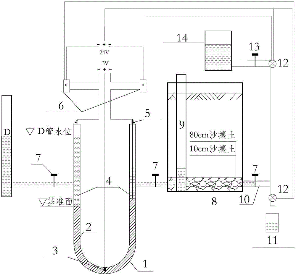
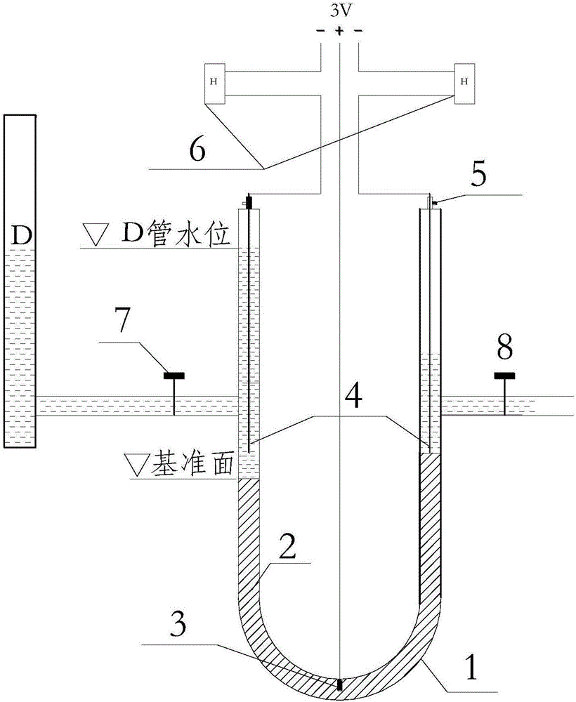
[0018] One side of the U-shaped pipe is connected to the underground water level observation well in Daejeon, and the other side is connected to the D pipe with a constant water volume. When the water level in the D pipe is the same as the water level in the water level observation well, the mercury column on both sides of the U-shaped pipe is equal. The plane is set as the base plane.

[0019] Adjust the adjustable contact 4 (which is an adjustable copper contact) to a certain height above the reference plane. Due to the large resistance of water, the 3V normally closed electromagnetic relay 6 controlled by the adjustable contact cannot reach the working voltage and is in the closed state (normally closed type is selected). Disabled.

[0020] When the external water level is higher than the internal water level (such as the field water level rises after a heavy rain...


PUM


Abstract

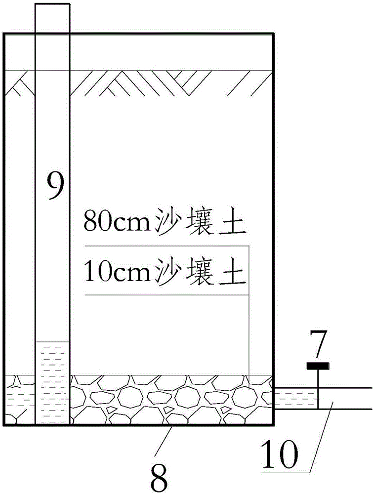
The invention relates to the automatic control device for underground water level, particularly to a system for realizing automatic-balancing sensing and control of a water level of a lysimeter. The system is composed of a U-shaped tube with liquid mercury, adjustable screw rods, adjustable contacts, a fixed contact arranged at the bottom of the U-shaped tube, a control valve, a water supply and measuring device, and a draining and measuring device. The adjustable screw rods and the adjustable contacts enable the liquid mercury and normally-closed electromagnetic relays to be connected. An upward opening is formed in the bottom of the U-shaped tube; and the fixed contact is arranged inside the opening at the bottom of the U-shaped tube and is connected with positive electrodes of the electromagnetic relays by wires. Outward openings are formed in the middle of the vertical tube walls at the two sides of the U-shaped tube; the water supply and measuring device is connected with the openings at the two sides of the U-shaped tube by conduits and is connected with an inlet and drain pipe buried in field by a flow control valve. The input terminals of the electromagnetic relays employ 3-V voltages. The U-shaped tube, the lysimeter, and the water supply and measuring device are connected in sequence. A water level observation well is arranged inside the lysimeter.

Description

technical field [0001] The invention relates to an automatic groundwater level control device, in particular to a system for automatically balancing, sensing and controlling the water level of a lysimeter, and more specifically, to a system suitable for areas where the groundwater level is shallow and changes rapidly, and is based on communication The principle of the lysimeter ensures that the lysimeter and the groundwater level of the field change synchronously, and the automatic balance sensor and control system of the lysimeter water level. Background technique [0002] In areas with shallow groundwater levels, groundwater recharge is an important component of crop water demand, which can reach 15% to 95% in some cases; under irrigation conditions, deep seepage can also reach about 10% or even higher of water demand. Due to the difficulty in measuring the amount of groundwater recharge and deep seepage in the field, the use of bottom lysimeter is a common method to study...

Claims


Application Information

Patent Timeline
IPC IPC(8): G05D9/12G01N33/24
CPCG05D9/12G01N33/246
Inventor 陈盛郭相平王振昌操信春
Owner HOHAI UNIV
Learn More