Electrode shaft driving device of extraction electrode
A technology for extracting electrodes and driving devices, applied in circuits, discharge tubes, electrical components, etc., can solve the problems of large rotation angle, poor adjustment accuracy, and inability to adjust small angles, and achieve high adjustment accuracy, continuous adjustment, and structure. simple effect
- Summary
- Abstract
- Description
- Claims
- Application Information
AI Technical Summary
Problems solved by technology
Method used
Image
Examples
Embodiment 1
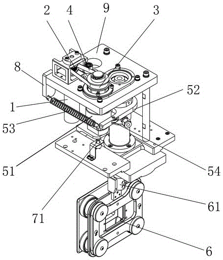
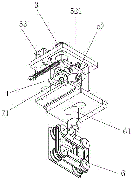
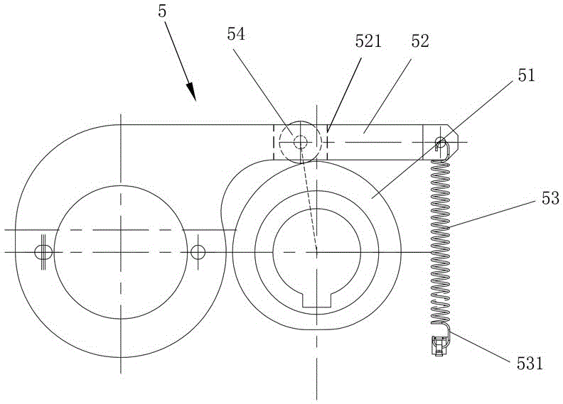
[0024] like Figure 1 to Figure 3 As shown, the electrode shaft driving device of the lead-out electrode of the present embodiment includes a motor 1, a driving pulley 2, a driven pulley 3 and a transmission belt 4 wound around the driving pulley 2 and the driven pulley 3, and the motor 1 The output shaft of the output shaft is connected with the wheel shaft of the driving pulley 2 through a coupling, and also includes a continuous adjustment assembly 5. The continuous adjustment assembly 5 includes a cam 51, a swing rod 52 and a ring for making the swing end of the swing rod 52 and the cam 51 close to each other. The elastic member 53 and the cam 51 are installed on the wheel shaft of the driven pulley 3, and the swing rod 52 is installed on the electrode shaft 61 of the lead-out electrode 6. The drive device installs the swing rod 52 on the electrode shaft 61, and the swing end of the swing rod 52 Closely attached to the cam 51, when the cam 51 rotates, it overcomes the elas...
Embodiment 2
[0029] like Figure 4 to Figure 5 As shown, the structure of the electrode shaft driving device for the lead-out electrode of this embodiment is basically the same as that of Embodiment 1, the difference is that the measurement of the rotation angle is realized by the multi-turn rotary potentiometer 72 installed on the motor 1 .
[0030] The working principle of the electrode shaft driving device for extracting electrodes of the present invention is as follows:
[0031] Start the motor 1, the motor 1 drives the driving pulley 2 to rotate, the driving pulley 2 drives the driven pulley 3 to rotate through the transmission belt 4, the cam 51 and the driven pulley 3 rotate synchronously, the cam 51 promotes the bearing 54 to move during the rotation process, and then The swing rod 52 is made to swing, and the swing of the swing rod 52 is converted into the rotation of the electrode shaft 61 , and finally the continuous adjustment of the electrode shaft 61 is realized.
PUM
 Abstract
Description
Claims
Application Information
 - R&D
- Intellectual Property
- Life Sciences
- Materials
- Tech Scout
- Unparalleled Data Quality
- Higher Quality Content
- 60% Fewer Hallucinations
Browse by: Latest US Patents, China's latest patents, Technical Efficacy Thesaurus, Application Domain, Technology Topic, Popular Technical Reports.
© 2025 PatSnap. All rights reserved.Legal|Privacy policy|Modern Slavery Act Transparency Statement|Sitemap|About US| Contact US: help@patsnap.com


