Laser power automatic control system

A technology of automatic power control and laser, which is applied to lasers, laser components, phonon exciters, etc., can solve problems such as complex circuit structure diagrams, and achieve the effect of reducing input current

Pending Publication Date: 2017-02-15
JIANGSU JUNLONG ELECTRIC TECH
View PDF5 Cites 1 Cited by
  • Summary
  • Abstract
  • Description
  • Claims
  • Application Information

AI Technical Summary

Problems solved by technology

However, the circuit structure diagrams of the above three methods are relatively complicated.

Method used


Image

  • Laser power automatic control system

Examples


Embodiment Construction

[0016] The present invention will be further explained below in conjunction with the accompanying drawings and specific embodiments. It should be understood that the following specific embodiments are only used to illustrate the present invention and are not intended to limit the scope of the present invention.

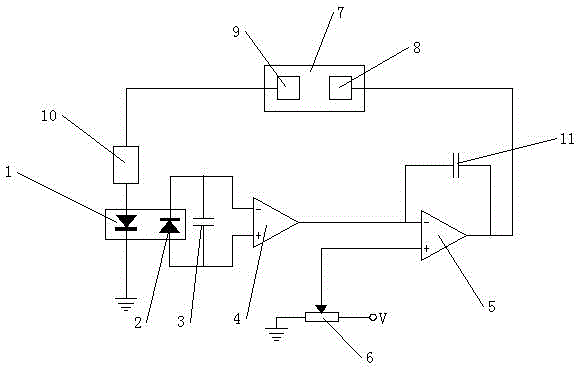
[0017] A laser power automatic control system, comprising a PIN tube 2 for detecting the backlight of the laser 1, the PIN tube 2 is installed on the side of the laser 1, the PIN tube 2 is connected with an operational amplifier 4, and the output terminal of the operational amplifier 4 is connected with a comparator 5 The negative terminal of the comparator 5 is connected to the DC reference voltage branch, the DC reference voltage branch is the current limiting resistor 6 set between the ground and the high potential of the reference voltage, and the middle tap of the current limiting resistor 6 is connected to At the positive end of the comparator 5, the output end o...


PUM


Abstract

The present invention provides a laser power automatic control system. The system comprises a PIN tube configured to detect the backlight of the laser, wherein the PIN tube is installed at the side of the laser and is connected in parallel with an operational amplifier; the output end of the operational amplifier is connected with the negative end of a comparator, and the positive end of the comparator is connected with a direct current reference voltage branch which is a current-limiting resistor arranged between the grounding and the high level with reference voltage; the center tap of the current-limiting resistor is connected with the positive end of the comparator, and the output end of the comparator is connected with a central control unit; and the laser is further connected with a switch power supply convertor, the central control unit includes an ADC convertor and a DAC convertor, and the pin of the DAC convertor of the central control unit is connected with the feedback voltage pin of the switch power supply convertor. The laser power automatic control system is simple in structure and can automatically control the power of the laser to allow the output power of the laser to keep basic constant.

Description

technical field [0001] The invention relates to a laser power automatic control system, in particular to a laser power automatic control system which has a simple structure and can make the laser output stable optical power. Background technique [0002] The world's first laser was born in 1960, and my country developed the first laser in 1961. Over the past 40 years, laser technology and applications have developed rapidly, and have been combined with multiple disciplines to form multiple application technology fields, such as photoelectric technology , laser medicine and photon biology, laser processing technology, laser detection and measurement technology, laser holography technology, laser spectrum analysis technology, nonlinear optics, ultrafast laser science, laser chemistry, quantum optics, laser radar, laser guidance, laser separation Isotopes, laser-controlled fusion, laser weapons, and more. The emergence of these intersecting technologies and new disciplines has g...

Claims


Application Information

Patent Timeline
IPC IPC(8): H01S3/131
CPCH01S3/131
Inventor 朱俊
Owner JIANGSU JUNLONG ELECTRIC TECH
Why Eureka
Try Eureka