Vital sign monitoring system

A vital sign and monitoring system technology, which is applied in telemetry patient monitoring, diagnostic recording/measurement, medical science, etc. It can solve the problems of large investment, untimely transmission of measurement data, and restrictions on the freedom of movement of patients, so as to achieve easy portability and use. , to ensure safe childbirth, and to measure the effect of high efficiency

Inactive Publication Date: 2017-02-22
智云康铠(北京)科技股份有限公司 +1
View PDF0 Cites 28 Cited by
  • Summary
  • Abstract
  • Description
  • Claims
  • Application Information

AI Technical Summary

Problems solved by technology

[0003] At present, most of the methods for detecting human vital signs are measured manually. When measuring such human physiological data, in order to eliminate the possibility that the special physiological parameters presented by the patient during a certain period of time are missed, contact measurement is generally required. Or real-time monitoring, such as wearing a blood pressure cuff device on the upper arm, and the monitoring device must be inflated to complete the detection of blood pressure; the device used to perform blood oxygen saturation measurement must be placed on the user's body, such as by means of a finger clip The measurement of heart rate and electrocardiogram needs to place ECG electrodes on the user's front chest. These existing monitoring devices and methods obviously limit the freedom of movement of the patient, and the patient must be monitored under the operation of professional medical personnel. During the monitoring , patients are p

Method used


Image

  • Vital sign monitoring system
  • Vital sign monitoring system
  • Vital sign monitoring system

Examples


Embodiment 1

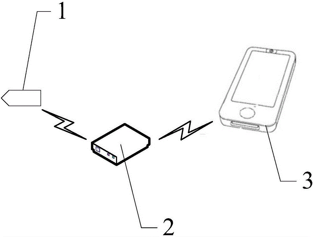
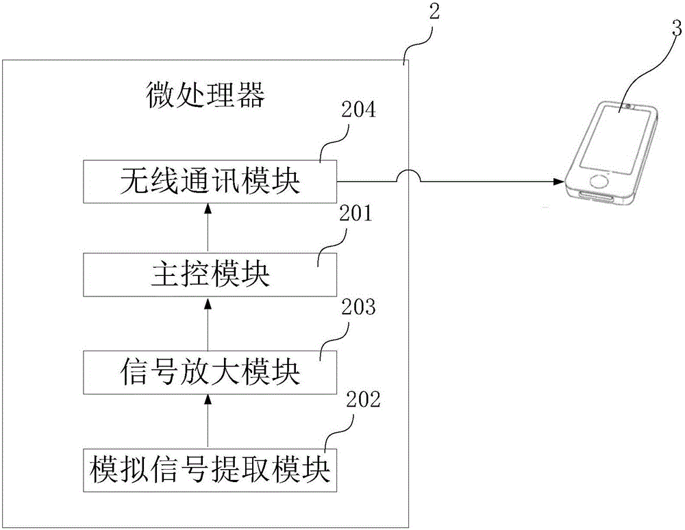
[0042] like figure 1 As shown in the figure, Embodiment 1 of the present invention provides a vital sign monitoring system, including a sensor and measurement component 1, a microprocessor 2 in communication with the sensor and measurement component 1, and a microprocessor 2 in communication with the microprocessor 2. Smart terminal 3, the sensing and measurement component 1 is used to collect vital sign information of the human body, convert the vital sign information into vital sign electrical signals and send to the microprocessor 2, the vital sign information includes body temperature, heart rate value, blood oxygen content, ECG data, EEG data. The sensing and measuring component 1 is a conductive electrode used to detect signals; the microprocessor 2 is mainly used to analyze and calculate the data. Of course, the microprocessor 2 can be connected to the host computer to process data through the host computer. The intelligent terminal 3 is used to receive the detection r...

Embodiment 2

[0047] Embodiment 2 of the present invention further defines the structure of the vital sign monitoring system on the basis of Embodiment 1, and improves the multi-functionality of the system.

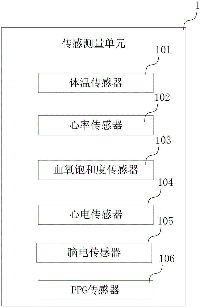
[0048] like image 3 As shown, it should be noted that the sensing and measurement component 1 includes a body temperature sensor 101 , a heart rate sensor 102 , a blood oxygen saturation sensor 103 , an electrocardiogram sensor 104 , and an electroencephalogram sensor 105 . Of course, the system can set different sensors according to different needs during production, and can set multiple sensors at the same time for simultaneous measurement. Different sensors are different conductive electrodes. For example, body temperature sensor 101 can be used to collect body temperature, heart rate sensor 102 can be used to collect heart rate, blood oxygen saturation sensor 103 can be used to collect blood oxygen content, and ECG sensor 104 can be used to detect ECG signals , the brain electric...

Embodiment 3

[0065] like Figure 7As shown, Embodiment 3 of the present invention is further defined on the basis of Embodiment 1. The monitoring system further includes a patch 11 that can be pasted on human skin, and the patch 11 includes at least two adhesive layers 5, Both the microprocessor 2 and the sensing and measuring component 1 are arranged between two adhesive layers 5 . The design of the patch 11 makes it more convenient for users to use. A microprocessor 2 and a sensing and measuring component 1 can be arranged between the two adhesive layers 5 to facilitate data collection and measurement. After the data is measured, it can be directly transmitted to the intelligent terminal 3. It can be uploaded to the cloud for storage.

[0066] like Figure 8-10 As shown, when in use, for example, the patch 11 is directly pasted on the chest, which can be used to measure the blood oxygen saturation of the user, pasted on the abdomen of a pregnant woman, can be used to monitor the fetal ...


PUM


Abstract

The invention provides a vital sign monitoring system. The system comprises a sensing measurement assembly, a microprocessor communicating with the sensing measurement assembly and an intelligent terminal communicating with the microprocessor; the sensing measurement assembly is used for collecting vital sign information of a human body, converting the vital sign information into a vital sign electric signal and sending the vital sign electric signal to the microprocessor, wherein the vital sign information comprises a body temperature value, a heart rate value, the blood oxygenation content, electrocardiogram data and electroencephalogram data. The vital sign monitoring system can be used for continuously measuring vital signs such as the body temperature, the heart rate, blood oxygen, electrocardio, electroencephalogram and blood pressure simultaneously, use of the system is convenient, the vital sign information can be measured continuously on the basis of not affecting daily life of a user, according to the system, automatic diagnosis and recognition on abnormal signals of the user are achieved through signal collection and signal analysis and processing, the burdens of medical staff are greatly reduced, carrying and use are convenient, and normal life of the user is not affected.

Description

technical field [0001] The invention relates to the technical field of medical electronic equipment, in particular to a vital sign monitoring system. Background technique [0002] For continuous medical-based monitoring of people or for training monitoring or recording, regular monitoring of human vital signs data is required, which can indicate a person's vital state, identify the presence of acute medical problems, as a rapid quantification of the level of disease and how well the body is Means of coping with combined physiological stress. Vital signs include the following key target clinical measurements: heart rate, respiration rate, body temperature, blood pressure, blood oxygen saturation under suitable conditions, electrocardiogram data, and electroencephalogram data, etc., which provide vital sign information about the patient's state of health. [0003] At present, most of the methods for detecting human vital signs are measured manually. When measuring such human ...

Claims


Application Information

Patent Timeline
IPC IPC(8): A61B5/0205A61B5/01A61B5/02A61B5/1455A61B5/0402A61B5/0476A61B5/0444A61B5/11A61B5/00A61B5/344
CPCA61B5/0004A61B5/0064A61B5/01A61B5/02A61B5/02055A61B5/02125A61B5/02411A61B5/02438A61B5/1118A61B5/14551A61B5/681A61B5/6824A61B5/6833A61B5/318A61B5/344A61B5/369
Inventor 许雪林
Owner 智云康铠(北京)科技股份有限公司
Why Eureka
Try Eureka