Automatic welding device for aluminum alloy longitudinal joints

An automatic welding and welding device technology, applied in auxiliary devices, welding equipment, auxiliary welding equipment and other directions, can solve the problems of high thermal conductivity, heat loss and slow speed of aluminum alloy materials, achieve prolonged cooling and solidification, prevent heat loss, The effect of improving welding efficiency

Inactive Publication Date: 2017-02-22
JIANGSU JINXIN ELECTRIC CO LTD
View PDF7 Cites 4 Cited by
  • Summary
  • Abstract
  • Description
  • Claims
  • Application Information

AI Technical Summary

Problems solved by technology

[0002] The aluminum alloy material has a high thermal conductivity, and the heat loss is serious during the welding process, which makes it difficult to obtain high-quality welds for automatic welding
This is because when welding some large aluminum alloy tubes, it is usually necessary to heat the welded place with a flame. Generally, a traditional drying gun is used for flame baking. Since the drying gun can only be heated in one place, the speed is slow, and the temperature in the local area The temperature is relatively high, and the local area temperature is low, which cannot guarantee the uniform heating of the welding area, which directly affects the welding effect of the workpiece.

Method used


Image

  • Automatic welding device for aluminum alloy longitudinal joints
  • Automatic welding device for aluminum alloy longitudinal joints
  • Automatic welding device for aluminum alloy longitudinal joints

Examples


Embodiment Construction

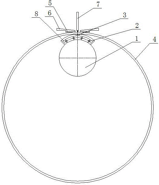
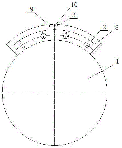
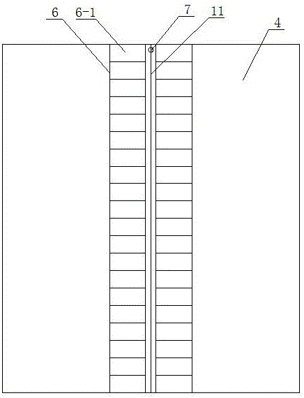
[0015] Such as figure 1 As shown in -3, the aluminum alloy longitudinal seam automatic welding device includes a mandrel 1 installed on the welding device frame, the axial direction of the mandrel 1 is consistent with the length direction of the longitudinal seam 11 of the workpiece 4, and the mandrel 1 is set on the 4 Below the longitudinal seam 11, an arc-shaped steel pipe 8 is arranged on the upper surface of the mandrel 1, and four electric heating pipes 2 are inserted in the arc-shaped steel pipe 8, and the four electric heating pipes 2 are evenly distributed along the arc direction of the arc-shaped steel pipe 8. . The upper surface of the arc-shaped steel pipe 8 is connected with a liner 3 , and the upper surface of the arc-shaped steel pipe 8 is provided with a liner installation groove 9 along the length direction, and the liner 3 is arranged in the liner installation groove 9 . A welding seam forming groove 10 is arranged on the upper surface of the pad 3 , and the ...


PUM


Abstract

The invention provides an automatic welding device for aluminum alloy longitudinal joints and relates to a structure of a welding lathe. The automatic welding device comprises a welding gun, a mandrel and two rows of key pressing finger assemblies, wherein each row of key pressing finger assemblies comprises a plurality of pressing fingers; an arc-shaped steel pipe is arranged on the upper surface of the mandrel, an electric heating pipe penetrates through the arc-shaped steel pipe, the upper surface of the arc-shaped steel pipe is connected with a liner, and the liner is arranged below a workpiece longitudinal joint; the length direction of the arc-shaped steel pipe, the length direction of the electric heating pipe and the length direction of the liner are all consistent with the length direction of the workpiece longitudinal joint; and a heat insulating plate is connected below each pressing finger, and the heat insulating plates are arranged on the outer surface of a workpiece for insulating heat. By adopting the mandrel electric heating, key pressing finger and product surface heat insulating mode, heat losses caused by heat conduction in a welding process are minimized, heat is used for fully melting aluminum materials in a concentrated manner, the cooling and condensation of a welding pool are prolonged, and oxides and gas in the pool fully overflow, so that high-quality weld joints are obtained, and the welding efficiency is increased.

Description

technical field [0001] The invention relates to the structure of a welding mechanism bed, in particular to an automatic longitudinal seam welding device for an aluminum alloy tube. Background technique [0002] The aluminum alloy material has a high thermal conductivity, and the heat loss is serious during the welding process, which makes it difficult for automatic welding to obtain high-quality welds. This is because when welding some large aluminum alloy tubes, it is usually necessary to heat the welded place with a flame. Generally, a traditional drying gun is used for flame baking. Since the drying gun can only be heated in one place, the speed is slow, and the temperature in the local area Higher, the temperature in the local area is lower, and the uniform heating of the welding area cannot be guaranteed, which directly affects the welding effect of the workpiece. Contents of the invention [0003] The object of the present invention is to overcome the deficiencies o...

Claims


Application Information

Patent Timeline
Patent Type & Authority Applications(China)
IPC IPC(8): B23K37/00B23K37/04
CPCB23K37/00B23K37/04
Inventor 李秀坤李兴康张金宝刘围琴汤金根
Owner JIANGSU JINXIN ELECTRIC CO LTD
Why Eureka
Try Eureka