Gas heat energy power system based on honeycomb cavity gasification

A power system and gas technology, applied in the direction of turbine/propellant fuel delivery system, charging system, gas turbine device, etc., can solve the problems of small external waste heat absorption rate, small amount of work, and large waste of heat energy, etc., to improve gasification efficiency and condensation efficiency, stable vaporization temperature and working medium flow rate, and the effect of reducing heat energy waste and cooling energy consumption

Pending Publication Date: 2017-02-22
郭远军
View PDF0 Cites 0 Cited by
  • Summary
  • Abstract
  • Description
  • Claims
  • Application Information

AI Technical Summary

Problems solved by technology

[0007] However, the common problems of existing thermal power generation equipment are: a. The temperature requirements for high-temperature heat sources are high, generally above 200°C, and the thermal energy conversion efficiency is low. The thermal energy conversion efficiency is generally 15% to 35%. Under the heat source of ℃, the average thermal energy conversion efficiency is 18%; b. The gasification of the working fluid in the gasification device is prone to incomplete gasification, the volume expansion is small, and the amount of external work in a single cycle of the gasification process is small; c. The gasification temperature is unstable, the condensation effect of the working medium is not good, and the working medium is easy to deteriorate or appear impurities; d. The driving force of the turbine is small, and the efficiency of converting the external work of the gasification medium into mechanical energy is low; e. The speed of the turbine is unstable, and It is prone to stuck problems; f. The heat collection effect of the heat collection device is not good, and the external waste heat absorption rate is small; g. The heat displacement of the condensing device is large, and the heat energy is wasted. The condensation speed through natural condensation is slow, and the use of Active condensation mode (fan air cooling or liquid pump water cooling) requires additional power consumption

Method used


Image

  • Gas heat energy power system based on honeycomb cavity gasification
  • Gas heat energy power system based on honeycomb cavity gasification
  • Gas heat energy power system based on honeycomb cavity gasification

Examples


Embodiment 1

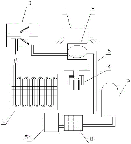
[0082] Embodiment one (such as figure 1 shown): a gas thermal energy power system based on honeycomb cavity gasification, including a heat collector 1, a gasification device 2, a turbine 3, a gas heating furnace 4, a condensation device 5, a circulation pipeline 6, a circulation medium 7 and The one-way hydraulic pump 9, the gasification device 2, the turbine 3, the condensing device 5 and the one-way hydraulic pump 9 realize circulation communication through the circulation pipeline 6 in sequence. The circulation pipeline 6 contains a circulating working medium 7, and the heat collection device 1 is installed Device 2 external;

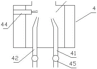
[0083] (like figure 2 As shown), the gas heating furnace 4 includes a gas inlet 41, an air inlet 42, a mixed gas combustion chamber 43 and an igniter 44, and the hot gas outlet of the mixed gas combustion chamber 43 is connected to the heat collector 1;

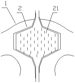
[0084] (like image 3 , Figure 4 As shown), the gasification device 2 includes a gasificat...

Embodiment 2

[0096] Embodiment two (such as Figure 9 shown): The difference from Embodiment 1 is that two layers of upper cover protruding rings 111 are distributed on the lower part of the upper cover 11 of the heat collecting device 1, and two layers of lower cover protruding rings are distributed on the upper part of the lower cover 12 of the heat collecting device 1. The ring 121, the upper cover protruding ring 111 and the lower cover protruding ring 121 are staggered.

[0097] By conducting experiments on the gas thermal energy power system based on honeycomb cavity gasification in the above-mentioned embodiment 2, gas is passed into the gas heating furnace 4, and the combustion temperatures in the gas heating furnace 4 are 120°C, 150°C, and 200°C respectively. , 250°C, 300°C, 400°C, the flow rate of the working medium in the circulation pipe is adjusted according to the operation stability of the gas thermal energy power system based on honeycomb cavity gasification; the experiment...

Embodiment 3

[0098] Embodiment three (such as Figure 10 Shown): The difference from Embodiment 1 is that the lower part of the upper cover 11 of the heat collecting device 1 is provided with a three-layer upper cover protruding ring 111, and the upper part of the lower cover 12 of the heat collecting device 1 is distributed with a three-layer lower cover protruding ring 121 , the upper cover protruding ring 111 and the lower cover protruding ring 121 are staggered.

[0099] By conducting experiments on the gas thermal energy power system based on honeycomb cavity gasification in the above-mentioned embodiment three, gas is fed into the gas heating furnace 4, and the combustion temperatures in the gas heating furnace 4 are 120°C, 150°C, and 200°C respectively. , 250°C, 300°C, 400°C, the flow rate of the working medium in the circulation pipe is adjusted according to the operation stability of the gas thermal energy power system based on honeycomb cavity gasification; the experimental resul...


PUM


Abstract

The invention discloses a gas heat energy power system based on honeycomb cavity gasification. The gas heat energy power system based on honeycomb cavity gasification comprises a gasifying device, a turbine, a condensing device and a one-way hydraulic pump for realizing circulating communication through circulating pipes; circulating working mediums are filled in the circulating pipes; the heat collecting device is mounted at the external of the gasifying device, and is communicated with a gas heating furnace; the gas heating furnace includes a gas inlet, an air inlet, a mixed gas combustion cavity and an igniter; the gasifying device includes a gasification cavity; the gasification cavity is a cavity for realizing gasification of a working medium in the gasifying device; the gasifying device is positioned in a heat collecting cavity; and the gasification cavity takes the shape of a honeycomb cavity. The gas heat energy power system based on honeycomb cavity gasification has such advantages as high gasification efficiency, high heat energy conversion efficiency and power adjustability.

Description

technical field [0001] The invention belongs to the field of energy utilization equipment, in particular to a gas thermal energy power system based on honeycomb cavity gasification. Background technique [0002] Energy is an important material basis for the survival and development of human society. Throughout the history of the development of human society, every major progress of human civilization is accompanied by the improvement and replacement of energy. The development and utilization of energy has greatly promoted the development of the world economy and human society. [0003] However, with the continuous development and consumption of energy, non-renewable energy sources such as petroleum, coal mines, and natural gas are gradually reduced, and energy conservation and recycling are gradually being valued. The basic content of my country's current energy strategy is: adhere to the priority of conservation, based on domestic, diversified development, rely on science...

Claims


Application Information

Patent Timeline
Patent Type & Authority Applications(China)
IPC IPC(8): F02C6/00F02C7/00F02C9/50F01K7/16F01K9/00F01K11/02F01K27/00
CPCF02C6/00F01K7/16F01K9/00F01K11/02F01K27/00F02C7/00F02C9/50
Inventor 郭远军
Owner 郭远军
Why Eureka
Try Eureka