Eureka AIR delivers breakthrough ideas for toughest innovation challenges, trusted by R&D personnel around the world.

Oxygen-enriched burner and air distribution method thereof

An oxygen-enriched combustion and air distribution technology, applied in the energy field, can solve problems such as insufficient combustion, slagging of water walls, high temperature corrosion, etc., and achieve the effects of improving flow field and flame shape, reducing ignition delay, and changing combustion atmosphere.

Inactive Publication Date: 2017-02-22
CHINA SHENHUA ENERGY CO LTD +3
View PDF3 Cites 2 Cited by
  • Summary
  • Abstract
  • Description
  • Claims
  • Application Information

AI Technical Summary

Problems solved by technology

Due to the change of the volume and composition of the gas entering the boiler, if the air distribution method used in the air combustion condition is still adopted, the flow field will change greatly, and it is difficult to form a good aerodynamic field in the furnace, resulting in poor combustion. Stablize
At the same time, in the existing air distribution method of the burner, the ratio method of oxygen in the primary air and the secondary air is not involved
In addition, due to the insufficient combustion caused by the existing air distribution method of the burner, the CO concentration in the oxygen-enriched combustion furnace increases, the reducing atmosphere on the wall surface increases, and it is easy to cause slagging and high-temperature corrosion of the water wall

Method used

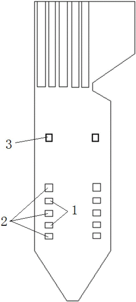
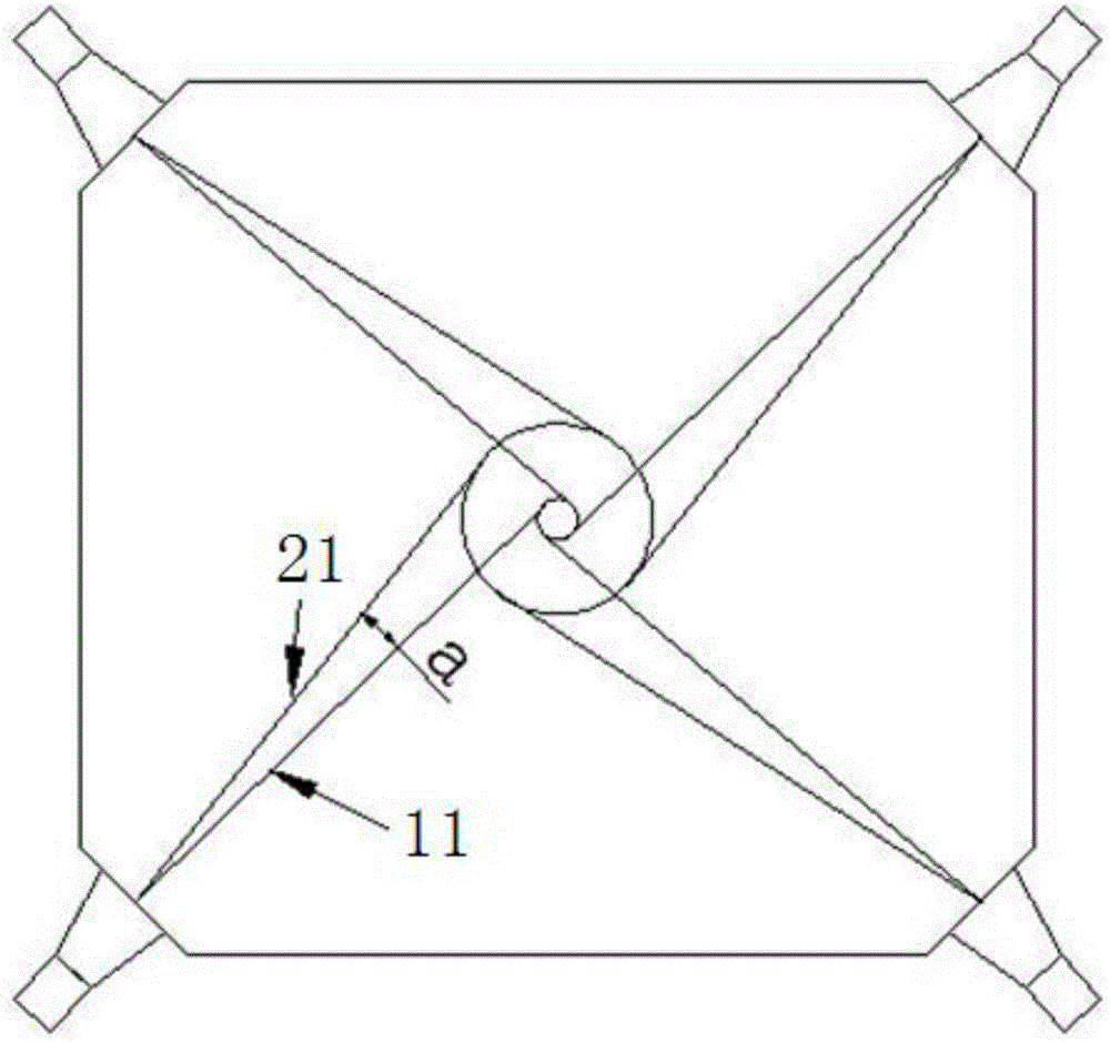
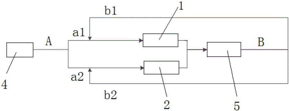

Image

  • Oxygen-enriched burner and air distribution method thereof
  • Oxygen-enriched burner and air distribution method thereof
  • Oxygen-enriched burner and air distribution method thereof

Examples


Embodiment Construction

[0035] Specific embodiments of the present invention will be described in detail below in conjunction with the accompanying drawings. It should be understood that the specific embodiments described here are only used to illustrate and explain the present invention, and are not intended to limit the present invention.

[0036] The following terms are involved in the present invention:

[0037] Oxygen coefficient: refers to the ratio of the amount of oxygen supplied per unit of pulverized coal to the amount of oxygen required for complete combustion of each unit of pulverized coal;

[0038] Oxygen: refers to relatively high-purity oxygen with a purity of 95% (volume fraction) and above;

[0039] Recirculated flue gas: refers to the flue gas that circulates into the boiler from the dust collector or flue gas condenser;

[0040] Flue gas circulation ratio: refers to the ratio of the total volume flow of circulating flue gas to the total volume flow of wet flue gas at the furnace...


PUM


Abstract

The invention relates to the technical field of energy, and discloses an oxygen-enriched burner and an air distribution method thereof. The burner comprises a combustion chamber, wherein a burnout air port, primary air ports and secondary air ports are formed in the wall of the chamber so as to form a line of air ports, the primary air ports and the secondary air ports are vertically formed below the burnout air port in the height direction of the combustion chamber at intervals, and the primary air ports are located between adjacent secondary air ports. The air distribution method of the oxygen-enriched burner comprises the steps of closing the burnout air port, and opening the primary air ports and the secondary air ports in the working condition of oxygen-enriched combustion; adjusting the volume of circulating smoke which enters a boiler and injected oxygen so as to adjust the oxygen partial pressure of the boiler; controlling a part of the injected oxygen to enter the primary air ports and the other part of the injected oxygen to enter the secondary air ports, and adjusting the oxygen partial pressure of primary air or secondary air; and controlling the momentum of the primary air to be the same as that of the primary air in the working condition of air combustion. According to the oxygen-enriched burner and the air distribution method, the high efficiency and stability of pulverized coal combustion are increased in the working condition from air combustion to oxygen-enriched combustion.

Description

technical field [0001] The invention relates to the field of energy technology, in particular to an oxygen-enriched burner and an air distribution method thereof. Background technique [0002] The burner is the main combustion equipment of the pulverized coal boiler. Its function is to send the fuel and the combustion-supporting agent required for combustion into the furnace through the combustion nozzle according to a certain ratio, speed and mixing method, so as to ensure that the fuel can be fully mixed with the combustion-supporting agent after entering the furnace. , timely ignition, stable combustion and burnout. Its reasonable organization of airflow in the furnace is a prerequisite for stable and efficient combustion of pulverized coal. [0003] Burners are divided into two categories according to their outlet airflow characteristics, one is a direct-flow burner, and the outlet airflow is a direct-flow jet group. The other type is a swirl burner, and the outlet air...

Claims


Application Information

Patent Timeline
Patent Type & Authority Applications(China)
IPC IPC(8): F23C7/02F23C9/06
CPCF23C7/02F23C9/003F23C9/06F23C2202/30Y02E20/32Y02E20/34
Inventor 柳朝晖刘毅郭军军王鹏黄晓宏郑楚光韩涛赵瑞黄卫军
Owner CHINA SHENHUA ENERGY CO LTD
Why Eureka
Eureka Blog
Learn More